Automatic exhaust system of clutch and exhaust method implemented by automatic exhaust system

An automatic exhaust and clutch technology, applied to clutches, fluid-driven clutches, non-mechanical drive clutches, etc., can solve problems such as poor environmental protection, low economic efficiency of transmission media, manual exhaust time-consuming and labor-intensive safety, etc., to achieve safety Improvement of performance and reliability, elimination of the possibility of failure, remarkable exhaust effect

Active Publication Date: 2014-04-02
陈小伟
View PDF8 Cites 6 Cited by
  • Summary
  • Abstract
  • Description
  • Claims
  • Application Information

AI Technical Summary

Problems solved by technology

[0004] The purpose of the present invention is to provide an automatic clutch exhaust system, which solves the problems in the prior art that the manual exhaust of the clutch is time-consuming, labor-intensive, low in safety, poor in environmental protection, and low in economical efficiency of the transmission medium itself.

Method used


Image

  • Automatic exhaust system of clutch and exhaust method implemented by automatic exhaust system
  • Automatic exhaust system of clutch and exhaust method implemented by automatic exhaust system
  • Automatic exhaust system of clutch and exhaust method implemented by automatic exhaust system

Examples


Embodiment 1

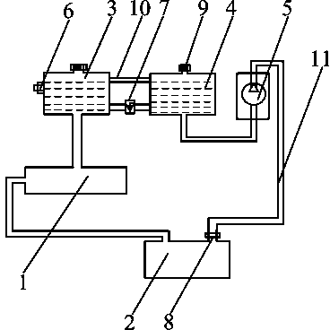
[0036] Such as figure 1 As shown, this implementation takes the air brake type clutch operating system as an example to describe the present invention in detail. The clutch automatic exhaust system mainly includes clutch master cylinder 1, clutch slave cylinder 2, liquid storage tank 3, compensation tank 4 and electric oil pump 5, wherein, compensation tank 4, electric oil pump 5, clutch slave cylinder 2, clutch master cylinder 1 and the liquid storage tank 3 are connected in sequence through the infusion pipeline 11, while the liquid storage tank 3 and the compensation tank 4 are connected through a conduit, and a check valve 7 is installed on the conduit, so that a medium is formed between each device flow loop. At the same time, an air conduit 10 is provided between the liquid storage tank 3 and the compensation tank 4 for gas flow between the liquid storage tank and the compensation tank. Considering that the gas must stay on the upper part of the liquid storage tank 3, ...

Embodiment 2

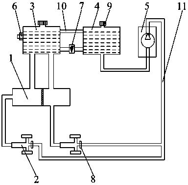
[0041] Such as figure 2 As shown, the present embodiment takes the hydraulic brake system single cylinder model as an example to illustrate the present invention. The difference from Embodiment 1 is that the brake cylinder includes a front cylinder and a rear cylinder, and the front cylinder and the rear cylinder The pumps are respectively provided with connecting bolts, and check valves are installed on the connecting bolts; the brake master cylinder is divided into a master cylinder front chamber and a master cylinder rear chamber, and the front sub-cylinder communicates with the liquid storage tank and the master cylinder front chamber respectively , and the rear slave pump is respectively connected with the liquid storage tank and the rear cavity of the master cylinder. The infusion pipeline coming out from the oil pump is respectively connected with the check valves on the front sub-pump and the rear sub-pump. As for the arrangement between the liquid storage tank, the c...

Embodiment 3

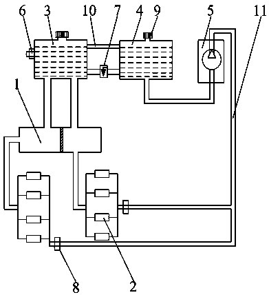
[0044] Such as image 3 As shown, this embodiment takes the hydraulic braking system double cylinder model as an example to illustrate the present invention. The pump belongs to the existing technology, not the design innovation of this technology, and this technology does not need to change the brake cylinder, so the above process will not be repeated here.

[0045] The invention can also be applied to the hydraulic braking system to realize the automatic exhaust of the hydraulic braking system. It should be noted that, from the above embodiments, it can be seen that the present invention can be applied to various clutch operating systems, and can realize automatic exhaust in a safe, convenient and efficient manner without affecting the normal operation of the clutch operating system. Its practical value and market prospect are very high.


PUM


Abstract

The invention discloses an automatic exhaust system of a clutch. The automatic exhaust system comprises a clutch master cylinder, clutch slave cylinders, a liquid storage tank, a compensation tank and an electric oil pump. The clutch master cylinder is communicated with the clutch slave cylinders, the liquid storage tank is communicated with the clutch master cylinder, the compensation tank is communicated with the liquid storage tank via an air guide pipe, the electric oil pump is communicated with each clutch slave cylinder by a liquid delivery pipeline, and the compensation tank is further communicated with the electric oil pump via another liquid delivery pipeline; a gas hole is further formed in the top of the compensation tank. The invention further discloses an exhaust method implemented by the automatic exhaust system of the clutch. According to the scheme, the automatic exhaust system and the exhaust method have the advantages that residual gas in an operating system of the clutch can be conveniently, efficiently, safely and thoroughly exhausted, accordingly, the problem of incomplete clutch separation due to incomplete exhaust can be solved, normal work of the operating system of the clutch can be guaranteed, faults can be prevented, and the automatic exhaust system and the exhaust method have extremely high application value and an excellent market prospect.

Description

technical field [0001] The invention relates to an automobile clutch, in particular to an automatic clutch exhaust system and an exhaust method thereof. Background technique [0002] Automobile clutch oil and gas operating system is one of the main operating systems of automobiles. In terms of composition and structure, it is mainly composed of clutch master cylinder, clutch slave cylinder, oil storage tank, exhaust bolt, pipe joint and oil pipe. During the use of the car, air often enters the clutch oil-air operating system, such as: disassembly and replacement of the clutch; seal leakage during the use of various components; air that is not exhausted during refueling; air resistance generated during clutch work, etc. , These gases stay in the clutch operating system, which will cause the clutch to disengage completely, and then lead to the failure of the clutch. Therefore, the exhaust effect determines the failure rate of the clutch to a large extent. [0003] At present,...

Claims


Application Information

Patent Timeline
Patent Type & Authority Applications(China)
IPC IPC(8): F16D25/12F15B21/04
Inventor 陈小伟
Owner 陈小伟
Why Eureka
Try Eureka