

Shifting method for AMT (Automated Mechanical Transmission) automatic gearbox
A technology of automatic transmission and gear shifting method, which is applied to transmission devices, fluid transmission devices, and components with teeth, etc., can solve problems such as clutch control difficulties, and achieve the effects of shortening shift time and reducing shift impact
- Summary
- Abstract
- Description
- Claims
- Application Information
AI Technical Summary
Problems solved by technology
Method used
Image

Examples
Embodiment Construction
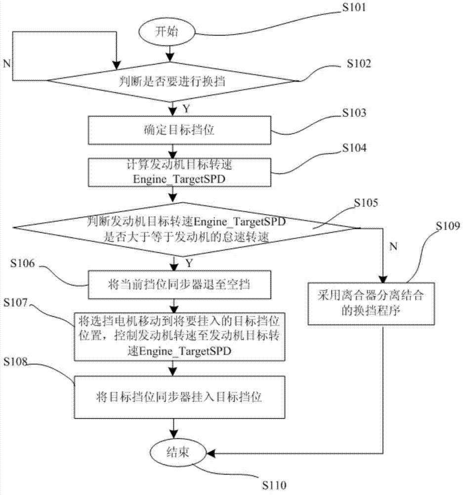
[0033] figure 1 It is a flow chart of the steps of the shifting method of the AMT automatic transmission according to an embodiment of the present invention. Such as figure 1 As shown, in the present embodiment, the shifting method of the present invention includes the following steps:
[0034] Step S101: The vehicle is turned on and starts to drive.
[0035] Step S102: During the driving process of the vehicle, the AMT automatic transmission is in any forward gear, judge whether it is necessary to shift gears to other forward gears according to the vehicle driving state parameters and the control signal, if it is necessary to shift gears, proceed to step 103 , otherwise repeat step S102.
[0036] Step S103: Determine the target gear to be shifted.
[0037] Step S104: According to the current vehicle speed and the gear ratio of the target gear, calculate the expected engine target speed Engine_TargetSPD when the clutch of the target gear is fully engaged.
[0038] Step S1...
PUM
 Abstract
Description
Claims
Application Information