Hose coupler

A technology of hose joints and pipe bodies, which is applied in the direction of hose connection devices, pipes/pipe joints/fittings, mechanical equipment, etc., which can solve the problems of weak connection, inability to use for a long time, falling off and leakage, etc., and achieve enhanced sealing High performance, easy connection and easy disassembly

Inactive Publication Date: 2014-04-02
天津渤海晟机械设备配件有限公司
View PDF0 Cites 2 Cited by
  • Summary
  • Abstract
  • Description
  • Claims
  • Application Information

AI Technical Summary

Problems solved by technology

This simple connection method is not firm, and it is prone to fall off and leakage, so it cannot be used for a long time

Method used


Image

  • Hose coupler

Examples


Embodiment Construction

[0014] The present invention will be described in detail below in conjunction with the accompanying drawings.

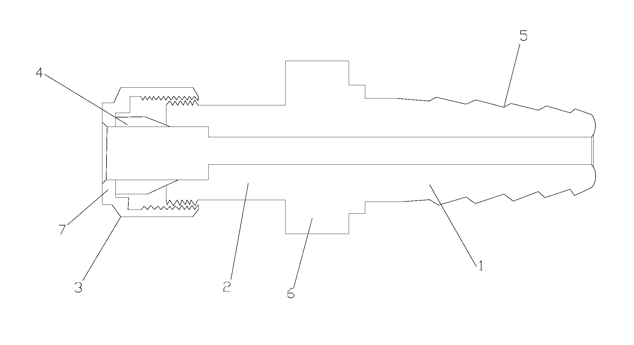
[0015] Such as figure 1 As shown, the present invention is a hose joint, which includes a connecting nozzle 1, a pipe body 2, a connecting nut 3 and a rubber pad 4. The outer surface of the connecting nozzle 1 is provided with an annular groove 5, and the connecting nozzle 1 is fixedly connected to the pipe body 2. , the rear part of the tube body 2 is provided with an external thread, the rear part of the tube body 2 is provided with a connecting nut 3 used in conjunction with the tube body 2, and a rubber pad 4 is arranged between the connecting nut 3 and the rear part of the tube body 2.

[0016] The middle part of the pipe body 2 is covered with a nut 6, and the nut 6 is fixed with the pipe body 2.

[0017] The end edge of the connecting nozzle 1 is arc-shaped.

[0018] An annular baffle 7 is arranged on the rear end surface of the connecting nut 3 .

[0019] ...


PUM


Abstract

The invention provides a hose coupler, which comprises a connection, a hose body, a connecting nut and a rubber pad, wherein an annular groove is arranged in the outer surface of the connection, the connection is fixedly connected to the hose body, external threads are arranged at the back of the hose body, the connecting nut matched with the hose body is arranged at the back of the hose body, the rubber pad is arranged between the connecting nut and the back of the hose body; the middle of the hose body is sleeved with a nut; an annular baffle is arranged on the back end face of the connecting nut. The hose coupler has the beneficial effects of firm connection, good sealing property and safety use.

Description

technical field [0001] The invention belongs to the field of connectors, in particular to a hose connector. Background technique [0002] For equipment using gas or liquid working medium, hoses are used for medium delivery pipelines, and the connection and use of various high and low pressure hoses is a relatively common phenomenon, especially with oxygen, gas, compressed air and nitrogen, hydrogen, argon This is especially true for thermal processing units that use , carbon dioxide gas, etc. as the working medium. The connection of hoses is generally connected by wire binding or pipe clamps (including extruded pipe clamps and screw tensioned pipe clamps). The common feature of these three connection methods is that the bundled or clamped hoses Inner shrinkage extrusion deformation is generated, relying on the anti-slip friction resistance between the inner surface of the hose or the inner surface of the inner tube and the outer surface of the connecting tube core (inverted...

Claims


Application Information

Patent Timeline
Patent Type & Authority Applications(China)
IPC IPC(8): F16L33/02
CPCF16L33/00F16L33/223
Inventor 王贵军
Owner 天津渤海晟机械设备配件有限公司
Why Eureka
Try Eureka