
Lifting slewer

A technology of rotary device and rotary shaft, which is applied in the direction of supporting machines, mechanical equipment, machine tables/supports, etc., to achieve the effect of accurate positioning, small movement impact, and no dead angle of testing

Inactive Publication Date: 2014-04-02
YICHANG ENHANCE ULTRASONIC ELECTRIC
View PDF0 Cites 5 Cited by
  • Summary
  • Abstract
  • Description
  • Claims
  • Application Information

AI Technical Summary

Problems solved by technology

[0002] In the underwater testing of ultrasonic transducers, it is usually necessary to use two devices, one for installing the ultrasonic transducer and the other for installing the test element. During the test, it is often necessary to change the ultrasonic transducer and Test the attitude of the component to obtain different data. In the prior art, there is no automatic control of the ultrasonic transducer without dead angles, and the full coverage of the ultrasonic transducer can be achieved, and the load can reach 1000kg, and a large lifting range can be achieved. installation

Method used


Image

  • Lifting slewer
  • Lifting slewer
  • Lifting slewer

Examples


Embodiment Construction

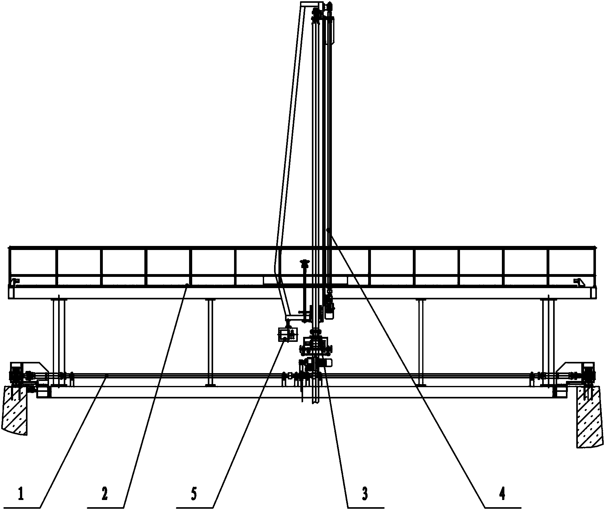
[0033] Such as figure 1 Among them, a lifting and turning device, including: a cart traveling system 1 for traveling along a guide rail;

[0034] The trolley traveling system 2 that walks on the cart traveling system 1;

[0035] Also includes: a support frame 19 installed on the trolley walking system 2;

[0036] The lifting and turning device 4 is provided on the support frame 19 .

[0037] The electrical control system 5 is an electrical control system composed of electrical control cabinets, low-voltage electrical components, and frequency conversion control systems. The whole system adopts PLC control, touch screen operation interface.

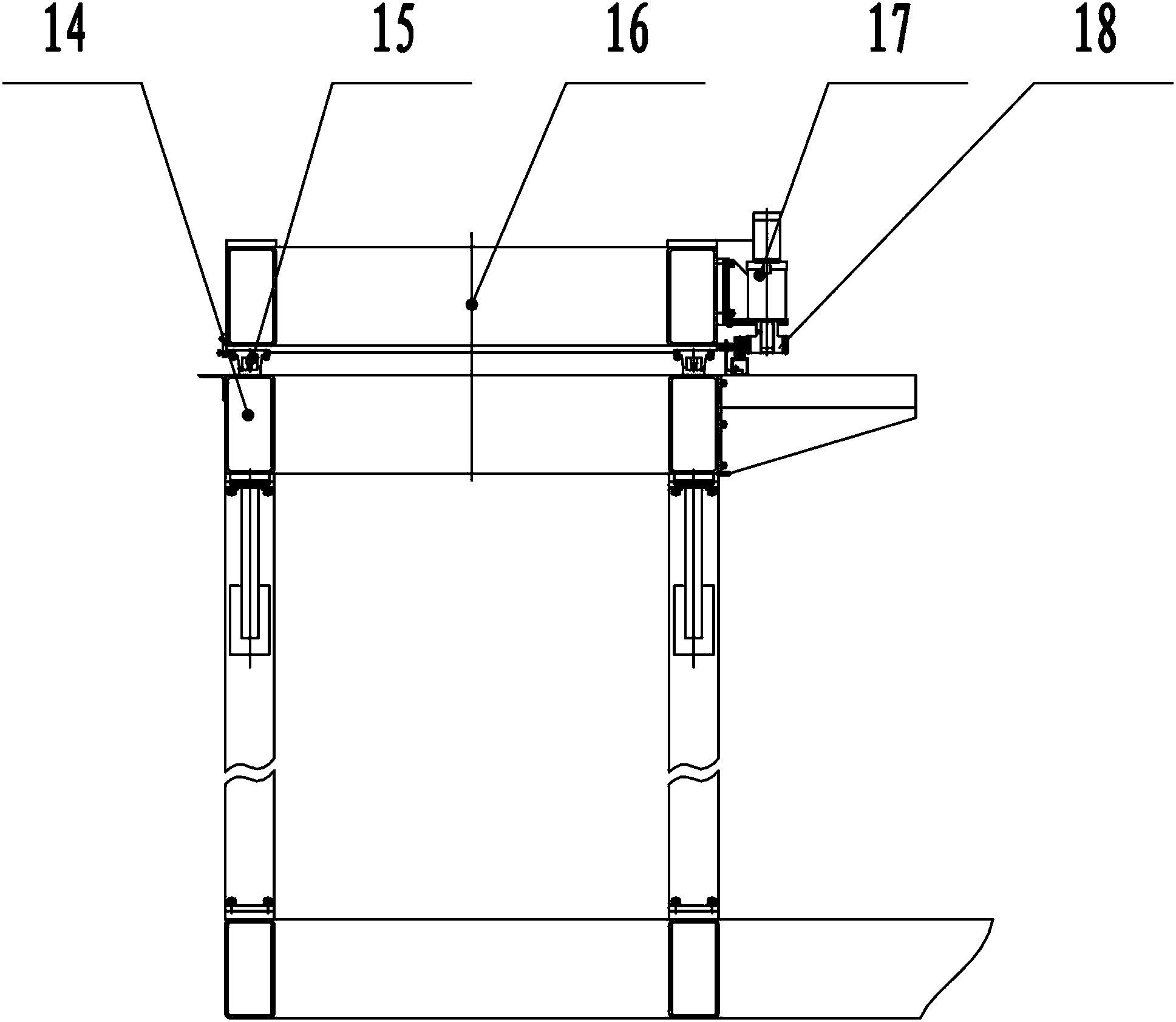
[0038] Such as figure 2 Among them, in the cart traveling system 1 described above, the cart reducer 12 installed on the cart support 7 is connected to the cart transmission shaft 8 through the cart gear transmission pair 10 and the cart coupling 11, and the cart transmission Axle 8 is connected with cart roller 9, and is used to dri...


PUM


Abstract

The invention discloses a lifting slewer, which comprises a cart running system for running along a guide rail, a trolley running system running on the cart running system, a supporting frame arranged on the trolley running system, and a lifting and turning device arranged on the supporting frame. In the lifting and turning device, a slewing mechanism is connected with the supporting frame through a lifting mechanism; the lifting mechanism is used for making the slewing mechanism lift along the supporting frame; the lower end of the slewing mechanism is provided with a pitching device for making a device thereon do pitching motion; the slewing mechanism is used for driving the pitching device to turn. By the structure, an ultrasonic transducer arranged on the lifting slewer can be automatically controlled to be located at any position of a pool in the travel of the lifting slewer, the ultrasonic transducer is positioned in any height in the lifting travel of the lifting and turning device and positioned at any rotation angle through the lifting and turning device on the lifting slewer, and the ultrasonic transducer is positioned at any pitching angle through the pitching device on the lifting slewer, so that a testing dead angle is avoided.

Description

technical field [0001] The invention relates to a device for realizing lifting and turning motion, in particular to a lifting and turning device for ultrasonic transducer testing to eliminate the dead angle of ultrasonic transducer testing. Background technique [0002] In the underwater testing of ultrasonic transducers, it is usually necessary to use two devices, one for installing the ultrasonic transducer and the other for installing the test element. During the test, it is often necessary to change the ultrasonic transducer and Test the attitude of the component to obtain different data. In the prior art, there is no automatic control of the ultrasonic transducer without dead angles, and the full coverage of the ultrasonic transducer can be achieved, and the load can reach 1000kg, and a large lifting range can be achieved. installation. Contents of the invention [0003] The technical problem to be solved by the present invention is to provide a lifting and turning d...

Claims


Application Information

Patent Timeline
Patent Type & Authority Applications(China)
IPC IPC(8): F16M11/42F16M11/06F16M11/04F16M11/18
Inventor 梁丽萍覃芝松高续业
Owner YICHANG ENHANCE ULTRASONIC ELECTRIC
Learn More