Oscillating rotor type expansion compressor

An expansion compressor, rotor type technology, applied in the direction of swing piston type machinery, compressor, swing piston type pump, etc., can solve the problems of short life of rolling bearing and large loss of clearance volume, so as to reduce friction loss and reduce clearance. Volume loss, beneficial effect on lubrication

Pending Publication Date: 2020-05-08
TIANJIN UNIV
View PDF0 Cites 0 Cited by
  • Summary
  • Abstract
  • Description
  • Claims
  • Application Information

AI Technical Summary

Problems solved by technology

In addition, the clearance volume loss of the inlet control system of the existing expander is relatively large, and the loss caused by the high-pressure fluid remaining in the suction line accounts for more than 50% of the total loss

Method used


Image

  • Oscillating rotor type expansion compressor
  • Oscillating rotor type expansion compressor
  • Oscillating rotor type expansion compressor

Examples


Example Embodiment

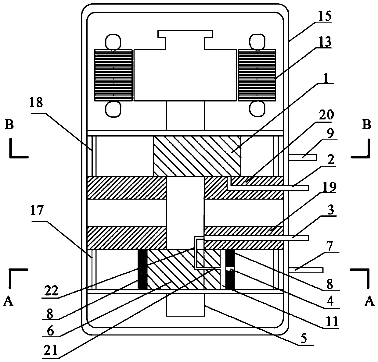
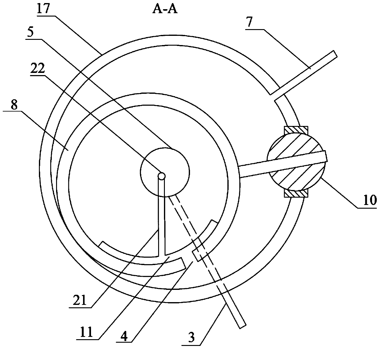
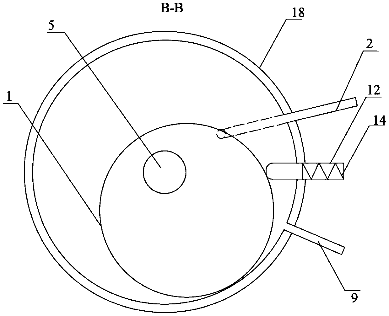
[0018] like Figure 1-3 The swing rotor type expansion compressor shown includes a housing 15, in which an expansion cylinder 17, a compression cylinder 18 and a motor 13 are arranged sequentially from bottom to top, and an expansion eccentric wheel 6 is arranged in the expansion cylinder 17, Compression cylinder 18 is provided with compression eccentric wheel 1, expansion eccentric wheel 6, compression eccentric wheel 1 and motor 13 are all fixedly connected with main shaft 5 axially arranged in the housing, in this embodiment, housing 15 is a cylinder , the main shaft 5 is parallel to the axial direction of the housing 15, the main shaft 5 runs through the expansion eccentric 6 and the compression eccentric 1, the motor 13 is fixedly installed inside the housing 15, and is used to drive the main shaft 5 to rotate, due to the expansion eccentric 6 and the compression eccentric The wheels 1 are integrated with the main shaft 5, so when the main shaft 5 rotates, both the expans...


PUM


Abstract

The invention provides an oscillating rotor type expansion compressor which comprises a shell. An expansion cylinder, a compression cylinder and a motor are arranged in the shell from bottom to top insequence. An expansion eccentric wheel is arranged in the expansion cylinder. A compression eccentric wheel is arranged in the compression cylinder. The expansion eccentric wheel, the compression eccentric wheel and the motor are all fixedly connected with a main shaft which is axially arranged in the shell. According to the oscillating rotor type expansion compressor provided by the invention, expansion work in the throttling process is recovered, and the loss of refrigeration capacity is reduced; and furthermore, frictional loss, moving impact, vibration and noise caused by mechanical moving parts are reduced.

Description

technical field [0001] The invention belongs to the technical field of heat pumps, and more specifically relates to a swing rotor type expansion compressor. Background technique [0002] In the refrigeration heat pump system, the supercritical carbon dioxide working medium can realize no pollution to the environment, and has good chemical stability and safety, and the cooling capacity per unit volume of the working medium is high. When the supercritical working medium enters the throttling element, it is generally in a supercritical state. After expanding in the throttling valve, it finally becomes a gas-liquid two-phase state. However, there is a large energy loss in the throttle valve using a capillary tube or a short throttle tube, which leads to low cycle efficiency. Therefore, an expansion valve is often used instead of the throttle valve. But how to utilize the recovered expansion work is an urgent problem to be solved. In addition, the clearance volume loss of the i...

Claims


Application Information

Patent Timeline
IPC IPC(8): F04C21/00F04C23/02F04C29/02F04C29/06F25B31/02
CPCF04C21/002F04C23/02F04C29/02F04C29/06F25B31/026
Inventor 王派马一太于宜禾张宁吴博昊詹浩淼李敏霞李昱翰
Owner TIANJIN UNIV
Why Eureka
Try Eureka