Vacuum cooling case

A vacuum and cold box technology, which is applied in the direction of color/spectral characteristic measurement, etc., can solve problems such as radial vibration and impact, reduced strength and stiffness, and fracture, so as to reduce stress, reduce wall thickness, and reduce cooling loss Effect

Inactive Publication Date: 2004-04-07
SHANGHAI INST OF TECHNICAL PHYSICS - CHINESE ACAD OF SCI
View PDF0 Cites 4 Cited by
  • Summary
  • Abstract
  • Description
  • Claims
  • Application Information

AI Technical Summary

Problems solved by technology

For this reason, thin-walled tubes with low thermal conductivity materials can be used to make the cantilever. The thinner the tube wall, the smaller the heat conduction and

Method used


Image

  • Vacuum cooling case
  • Vacuum cooling case
  • Vacuum cooling case

Examples


Example Embodiment

[0017] The present invention will now be described in detail with reference to the drawings.

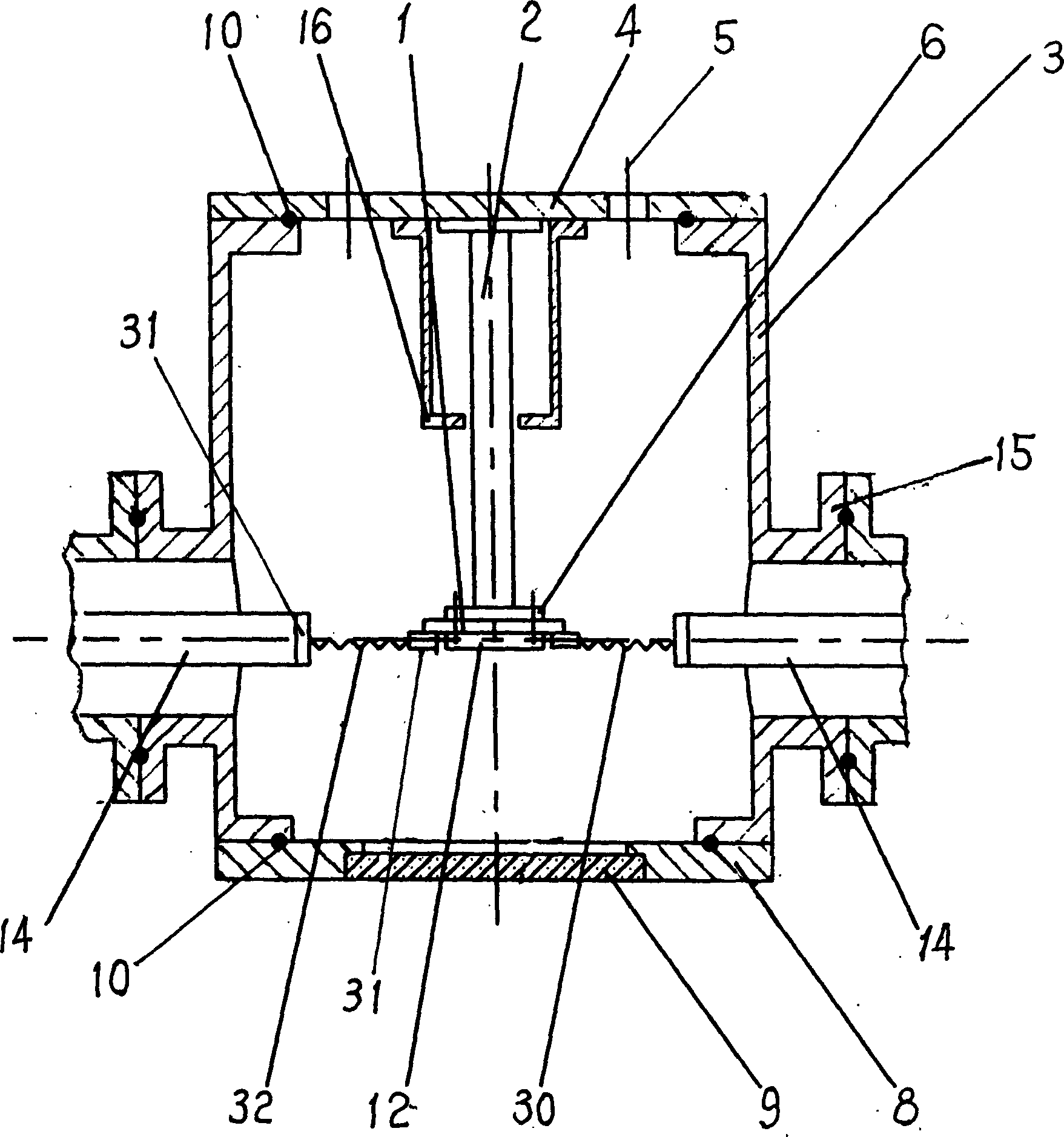
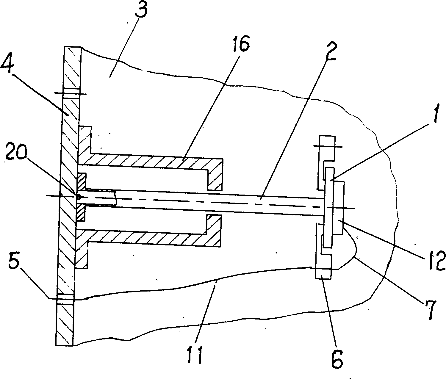
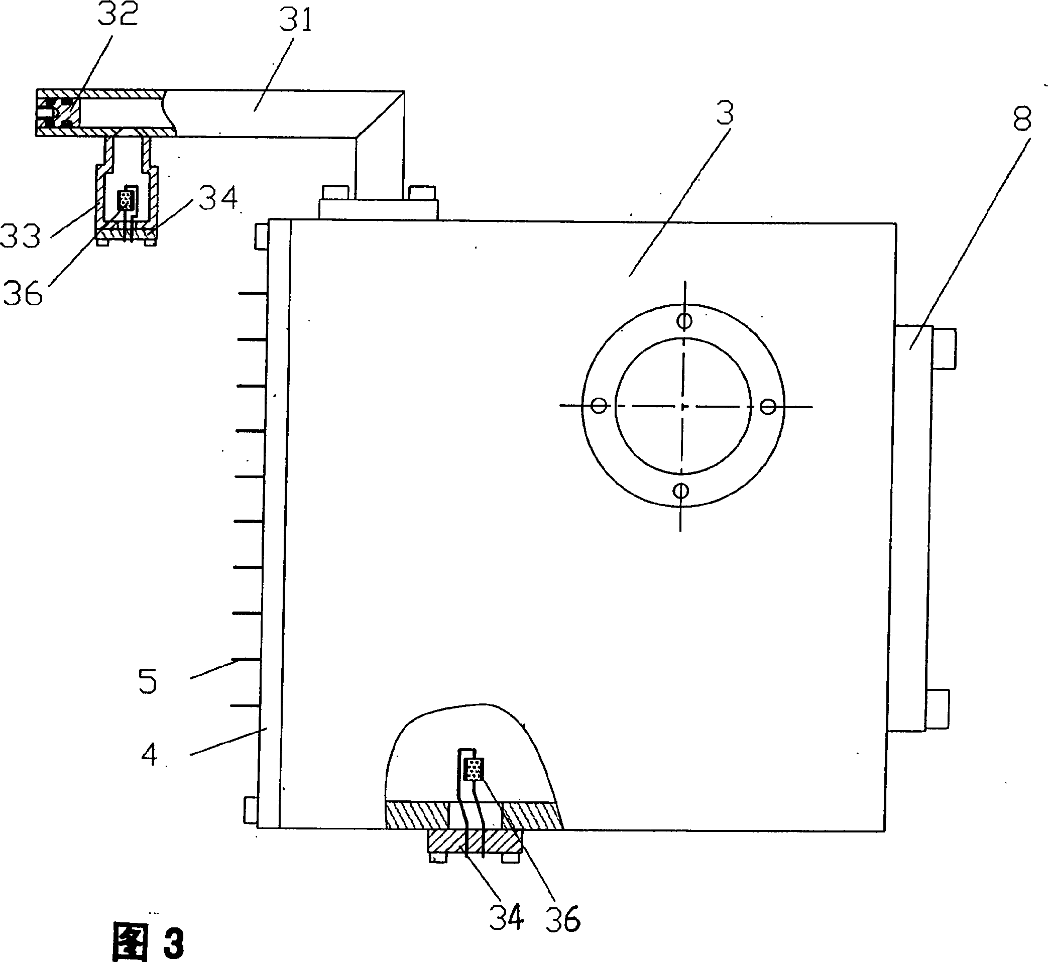
[0018] See figure 1 with figure 2 As shown, the vacuum cold box of the present invention includes a box body 3, a cold platform 1 and a cantilever 2. The front of the box body 1 is provided with a light-passing window composed of a window frame flange 8 and an infrared transparent window 9, and a sealing ring 10 is arranged in between for vacuum sealing and fixed with screws. The light signal enters through the light window for detection by the infrared detector 12 placed on the cold platform 1. The rear wall of the box body 3 is a sealed cable plate 4 with output lead pins 5, which are fixed on the box body 3 by screws. The rear end of the cantilever 2 is fixed on the sealed cable plate 4, and the front end of the cantilever 2 suspended in the box body 3 fixes the cold platform 1. The cantilever 2 is a thin-walled tube made of low thermal conductivity material. Its two ends are closed ...


PUM


Abstract

The vacuum cooling case includes case, cooling platform and cantilever; and features the cantilever of low heat conductivity thin wall pipe; position limiting sleeve around the cantilever and micro annular interval between the cantilever and the position limiting sleeve. The present invention solves the technological problems related to lowering the heat conducting cold consumption of the cantilever and raising the resistance to radial vibration and shock of the cantilever.

Description

Technical field: [0001] This invention relates to cooling, in particular to vacuum cold boxes for infrared detector storage and cryogenic operation. Background technique: [0002] The infrared detector works at low temperature, which can reduce its internal thermal noise and improve the detector sensitivity, responsivity and signal-to-noise ratio. To this end, the highly sensitive infrared detectors all use vacuum interlayer Dewar containers or vacuum cold boxes to provide a low-temperature working environment. Moreover, many effective technical solutions have been proposed for the vibration problem of the refrigerator that affects the work of the infrared detector. The infrared detector is fixed on the cold platform of the vacuum cold box, and the cold platform is supported in the box space by a cantilever fixed on the rear wall of the box. In order to reduce the cooling loss on the cold platform as much as possible, the cantilever should not only have sufficient strength...

Claims


Application Information

Patent Timeline
IPC IPC(8): G01N21/35
Inventor 纪国林刘晓华许妙根
Owner SHANGHAI INST OF TECHNICAL PHYSICS - CHINESE ACAD OF SCI
Why Eureka
Try Eureka