

Cooler, heat sink and electronic apparatus
A technology for radiators and cooling equipment, applied in the direction of cooling/ventilation/heating transformation, circuits, electrical components, etc., can solve the problems of increasing heat dissipation, achieve the effects of reducing exhaust volume, easy formation, and reduced production costs
- Summary
- Abstract
- Description
- Claims
- Application Information
AI Technical Summary
Problems solved by technology
Method used
Image

Examples
no. 1 example
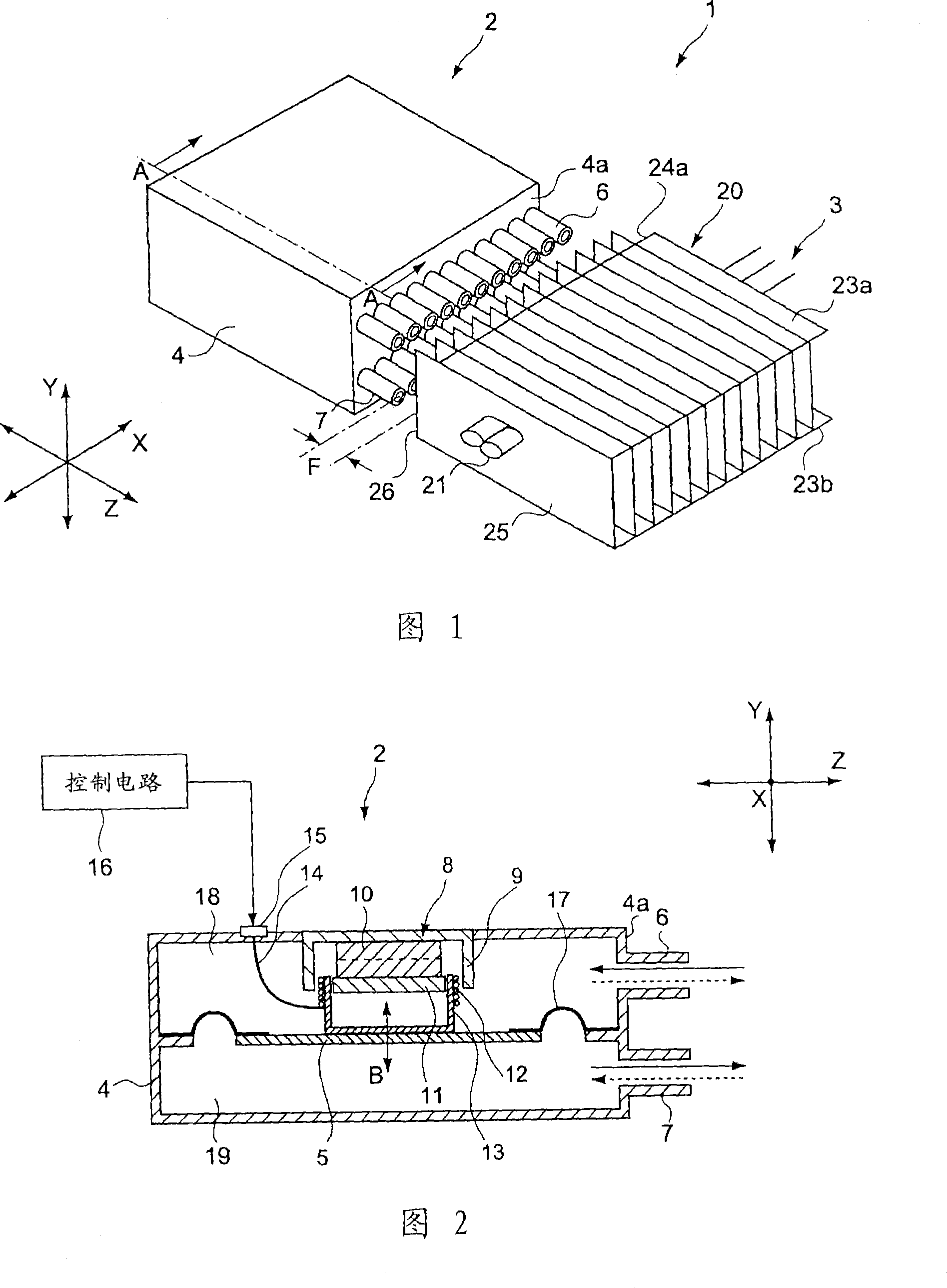
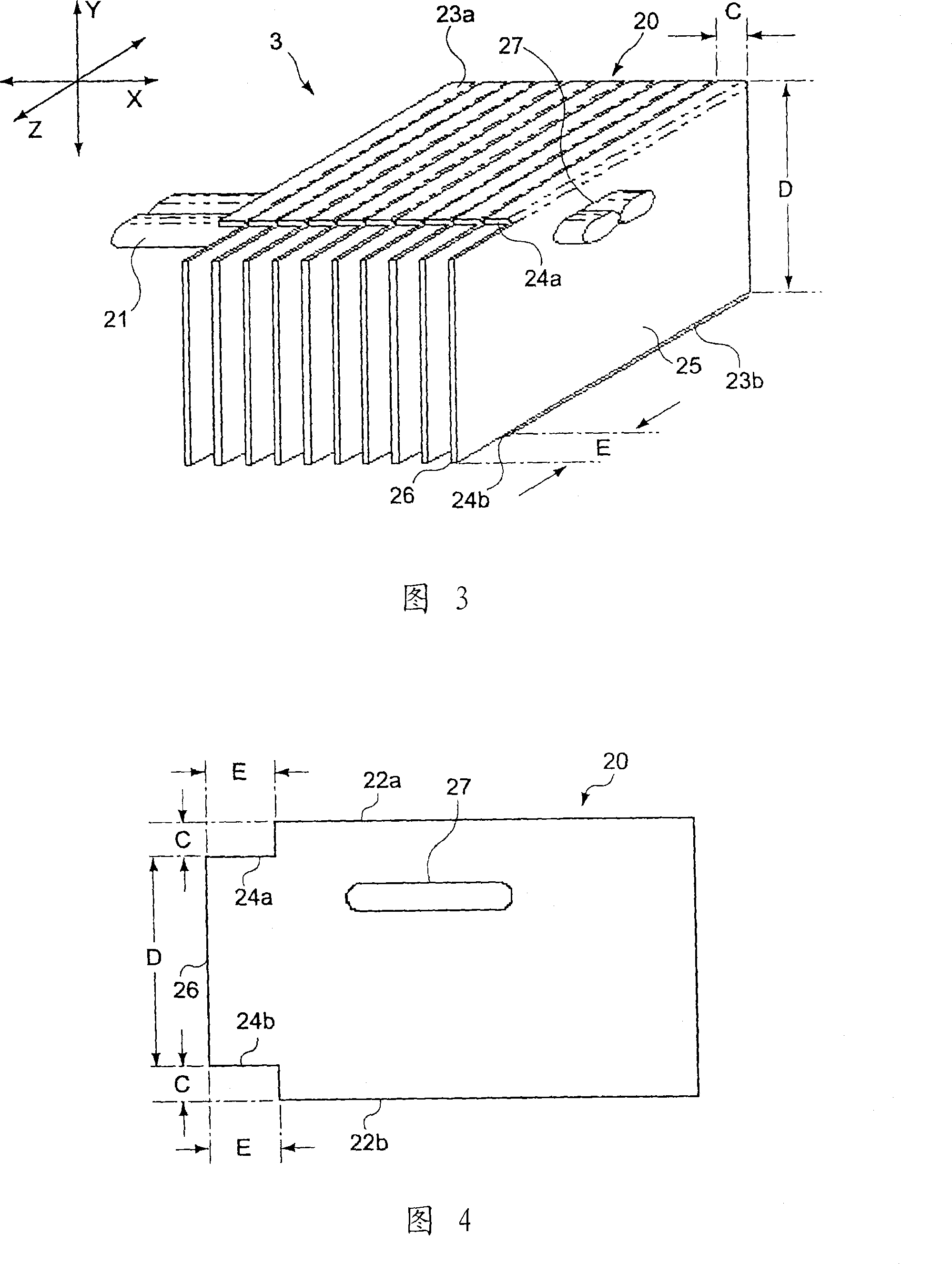
[0068] 1 is a perspective view of a cooling device according to a first embodiment of the present invention, FIG. 2 is a sectional view along line A-A of FIG. 1, and FIG. 3 is a perspective view of a radiator.
[0069] (Structure of cooling equipment)
[0070] The cooling device 1 includes a spray generating mechanism 2 that discharges a pulsating flow of gas, and a radiator 3 that receives the gas discharged from the spray generating mechanism 2 , as shown, for example, in FIG. 1 .
[0071] The ejection generating mechanism 2 includes, for example, a housing 4 containing gas, and a vibrating plate 5 as a vibrating body vibratingly installed in the housing.
[0072] For example, as shown in FIG. 1 , a plurality of first nozzles 6 serving as first openings, and a plurality of second nozzles 7 serving as second openings are provided on one side 4 a of the case 4 . The first and second nozzles 6 and 7 discharge the air used as gas contained in the housing 4 toward the radiator 3...
no. 2 example
[0120] Fig. 9 is a perspective view of a heat sink according to a second embodiment of the present invention.
[0121] This embodiment differs from the first embodiment in that the partition sheet is connected to the radiation sheet of the heat sink. Therefore, the description below will focus on this difference.
[0122] The heat sink 103 includes a plurality of radiating fins 20 which receive air as exhaust gas from the ejection generating mechanism 2; heat pipes 21 as heat conduction members which transfer heat from a heat source to the radiating fins 20; The midpoint between the two nozzles 6 and 7 is, for example, as shown in FIG. 9 .
[0123] The partition sheet 130 is disposed on the side of the radiation sheet 20 receiving gas exhausted from the injection generating mechanism 2 and between the first and second nozzles 6 and 7 of the injection generating mechanism 2 . The partition piece 130 extends in a direction substantially orthogonal to a straight line connecting...
no. 3 example
[0147] Fig. 12 is a perspective view of a heat sink according to a third embodiment.
[0148] This embodiment differs from the first embodiment in that the heat pipe of the heat sink does not extend through the radiation sheet, but is arranged on the face of the curved side portion 23a or 23b of the radiation sheet. Therefore, the description below will focus on this difference.
[0149] The heat sink 203 includes a plurality of radiation fins 20 which receive air as exhaust gas from the injection generating mechanism 2; heat pipes 221 which serve as heat conduction members which transfer heat from a heat source to the radiation fins 20; The partition piece 130 between and 7 is, for example, as shown in FIG. 12 .
[0150] The heat pipe 221 is partially welded and thermally connected to the face of the curved side portion 23a of the radiation sheet 20, for example, as shown in FIG. 12 .
[0151] Since the cross section of the heat pipe 221 is substantially elliptical, the con...
PUM
 Abstract
Description
Claims
Application Information