
A Fiber Optic Gyroscope with Low Random Walk Coefficient

A fiber optic gyroscope and polarization-maintaining fiber technology, which is applied to Sagnac effect gyroscopes, gyroscopes/steering sensing devices, measuring devices, etc. Effects of random walk coefficients

Inactive Publication Date: 2016-03-16
中国兵器工业导航与控制技术研究所
View PDF5 Cites 0 Cited by
  • Summary
  • Abstract
  • Description
  • Claims
  • Application Information

AI Technical Summary

Problems solved by technology

By increasing the diameter of the fiber optic loop and increasing the length of the light, it will increase the volume and limit the application range of the fiber optic gyroscope, especially the price of polarization maintaining fiber is relatively expensive, which will increase the cost of the fiber optic gyroscope

Method used


Image

  • A Fiber Optic Gyroscope with Low Random Walk Coefficient
  • A Fiber Optic Gyroscope with Low Random Walk Coefficient

Examples


Embodiment Construction

[0017] In order to make the object, technical solution and advantages of the present invention clearer, the present invention will be further described in detail below in conjunction with specific embodiments and with reference to the accompanying drawings.

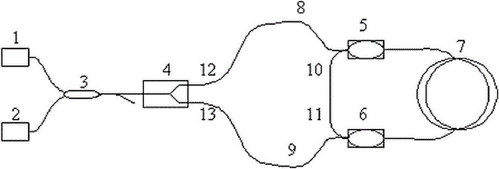
[0018] figure 1 It is a structural schematic diagram of the fiber optic gyroscope of the present invention. Such as figure 1 As shown, the fiber optic gyroscope with low random walk coefficient of the present invention consists of a wide-spectrum light source 1, an optical detector 2, a 2*2 coupler 3, an integrated optical modulator 4, a first polarization-maintaining beam splitter 5, and a second polarization-maintaining beam splitter. It is composed of a partial beam splitter 6 and an optical ring 7.

[0019] Among them, the broadband light source 1 is used to generate broadband light for the entire fiber optic gyroscope to effectively reduce the non-reciprocal phase shifts of the fiber optic gyroscope. The superlumin...


PUM


Abstract

The invention discloses a fiber-optic gyroscope which comprises a wide spectrum light source, an optical detector, a 2*2 coupler, an integrated optic modulator, a first polarization-maintaining beam splitter, a second polarization-maintaining beam splitter and a fiber loop, wherein the 2*2 coupler is used for splitting light from the wide spectrum light source, then enabling the split light to enter the integrated optic modulator, and transferring an interfered optical signal into the optical detector in split beams; the integrated optic modulator is used for polarizing and splitting beams of a light path, fast axis branches and slow axis branches of the first polarization-maintaining beam splitter and the second polarization-maintaining beam splitter are coupled with a fast axis of a tail fiber of the integrated optic modulator, the first branch of the integrated optic modulator is in countershaft welding with the fast axis branch of the first polarization-maintaining beam splitter, the second branch of the integrated optic modulator is in countershaft welding with the slow axis branch of the second polarization-maintaining beam splitter, the slow axis branch of the first polarization-maintaining beam splitter is in countershaft welding with the fast axis branch of the second polarization-maintaining beam splitter, and single-ended tail fibers of the first polarization-maintaining beam splitter and the second polarization-maintaining beam splitter are respectively in countershaft welding with two tail fibers of the fiber loop.

Description

technical field [0001] The invention relates to an optical gyro instrument, in particular to an interference type optical fiber gyro instrument which adopts a connection method of a polarization maintaining beam splitter and an optical fiber ring to improve the random walk coefficient of the optical fiber gyro. Background technique [0002] The fiber optic gyroscope is an all-solid-state optical gyroscope based on the Sagnac effect. Fiber optic gyroscope has developed rapidly since its first appearance in 1976. So far, it has completely replaced the traditional mechanical gyroscope in many fields and has become the mainstream device in the field of modern navigation. [0003] An important parameter in fiber optic gyroscope is the random walk coefficient. In different applications, fiber optic gyroscopes are required to have different accuracy. The random walk coefficient is an important indicator of the accuracy of the fiber optic gyroscope, that is, the higher the applicat...

Claims


Application Information

Patent Timeline
Patent Type & Authority Patents(China)
IPC IPC(8): G01C19/72
CPCG01C19/725
Inventor 肖新东郑吉兵于洪涛张敏施洋
Owner 中国兵器工业导航与控制技术研究所
Learn More