A cross-voltage domain data transmission method, voltage domain subsystem and electronic equipment
A data transmission method and technology of electronic equipment, applied in the field of cross-voltage domain data transmission method, voltage domain subsystem and electronic equipment, can solve the problems of unstable data transmission, difficult synchronization of clock signal timing, etc., and achieve easy and stable transmission, realization The effect of stable transmission
- Summary
- Abstract
- Description
- Claims
- Application Information
AI Technical Summary
Problems solved by technology
Method used
Image

Examples
Embodiment 1
[0025] In Embodiment 1 of the present invention, the electronic device includes two voltage domain subsystems, a first voltage domain subsystem and a second voltage domain subsystem. For example, the first voltage domain subsystem may be a CPU (Central Processing Unit, central processing unit) device) subsystem, the second voltage domain subsystem may be an SOC subsystem; or the first voltage domain subsystem may be an SOC subsystem, and the second voltage domain subsystem may be a CPU subsystem. When performing data transmission between the two, the following data transmission method can be used, and this data transmission method can also be applied to the process of implementing dynamic voltage frequency adjustment in the chip of the electronic device, and the second voltage domain subsystem sends the first voltage domain The subsystem transmits data as an example, such as figure 2 As shown, the cross-voltage domain data transmission method provided by Embodiment 1 of the p...
Embodiment 2
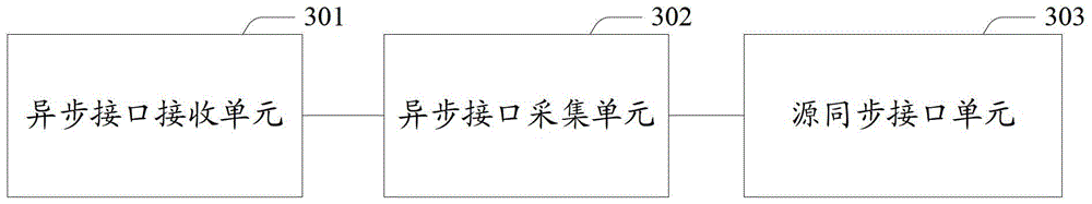
[0042] Based on the same inventive concept, according to the data transmission method across the voltage domain provided by the above-mentioned embodiments of the present invention, correspondingly, Embodiment 2 of the present invention also provides a voltage domain subsystem in an electronic device, and its structural diagram is as follows image 3 shown, including:
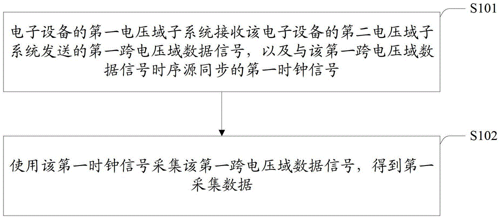
[0043] An asynchronous interface receiving unit 301, configured to receive the first cross-voltage domain data signal sent by the second voltage domain subsystem of the electronic device, and the first clock signal synchronized with the timing source of the first cross-voltage domain data signal;
[0044] The asynchronous interface collection unit 302 is configured to use the first clock signal to collect the first cross-voltage domain data signal to obtain first collection data.
[0045] The above-mentioned asynchronous interface receiving unit 301 and the asynchronous interface collecting unit 302 may jointly...
Embodiment 3
[0050] Based on the same inventive concept, according to the cross-voltage domain data transmission method provided by the above-mentioned embodiments of the present invention, correspondingly, Embodiment 3 of the present invention also provides an electronic device, the structural diagram of which is as follows Figure 4 As shown, it includes: a first voltage domain subsystem 402 and a second voltage domain subsystem 401, wherein:
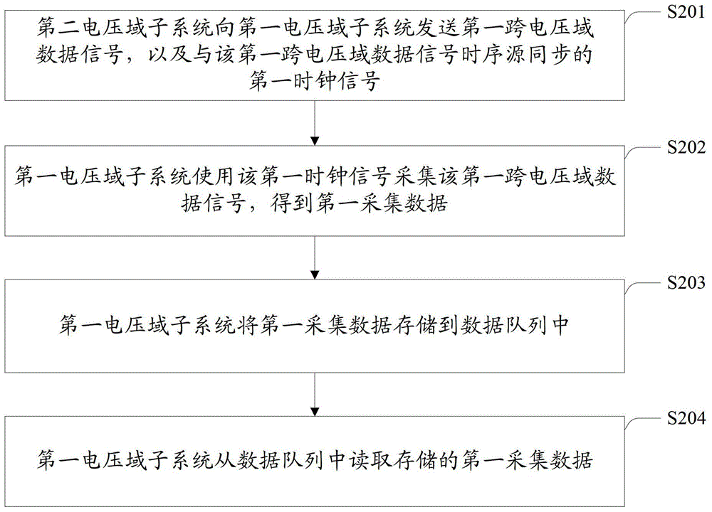
[0051] The second voltage domain subsystem 401 is configured to send a first cross-voltage domain data signal to the first voltage domain subsystem 402, and a first clock signal synchronized with the timing source of the first cross-voltage domain data signal;
[0052] The first voltage domain subsystem 402 is configured to receive the first cross-voltage domain data signal and the first clock signal; and use the first clock signal to collect the first cross-voltage domain data signal to obtain first collection data.
[0053] Further, the above-me...
PUM
 Abstract
Description
Claims
Application Information
 - R&D
- Intellectual Property
- Life Sciences
- Materials
- Tech Scout
- Unparalleled Data Quality
- Higher Quality Content
- 60% Fewer Hallucinations
Browse by: Latest US Patents, China's latest patents, Technical Efficacy Thesaurus, Application Domain, Technology Topic, Popular Technical Reports.
© 2025 PatSnap. All rights reserved.Legal|Privacy policy|Modern Slavery Act Transparency Statement|Sitemap|About US| Contact US: help@patsnap.com