Grid electrode driving circuit and display device

A gate drive circuit and gate drive technology, applied in static indicators, instruments, etc., can solve problems such as high cost, short circuit or open circuit, and achieve the effects of reducing short circuit or open circuit, reducing the number, and reducing the volume

Active Publication Date: 2014-04-02
HEFEI BOE OPTOELECTRONICS TECH +1
View PDF5 Cites 34 Cited by
  • Summary
  • Abstract
  • Description
  • Claims
  • Application Information

AI Technical Summary

Problems solved by technology

[0005] In view of this, the present invention provides a gate drive circuit and a display device to solve the problem that the display device in the prior art requires a plurality of gate drive circuit chips, which leads to high cost and is easy to cause defects such as short circuit or open circuit.

Method used


Image

  • Grid electrode driving circuit and display device
  • Grid electrode driving circuit and display device
  • Grid electrode driving circuit and display device

Examples


Embodiment Construction

[0040] In order to make the technical problems, technical solutions and advantages to be solved by the present invention clearer, the following will describe in detail with reference to the drawings and specific embodiments.

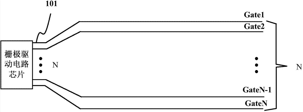
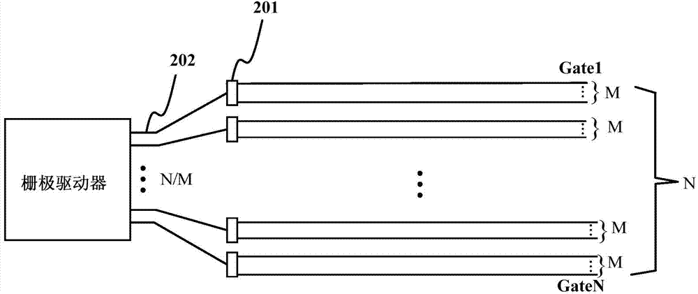
[0041] In order to solve the problem that the display device in the prior art requires a plurality of gate drive circuit chips, resulting in high cost and easy short circuit or open circuit, etc., an embodiment of the present invention provides a gate drive circuit, including:

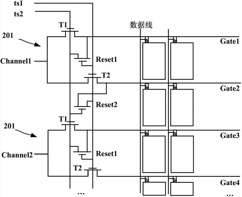
[0042] A plurality of gate drive units, each gate drive unit is respectively connected to a pulse signal input terminal, a timing control signal input terminal and at least two adjacent gate scanning lines, for inputting the timing control signal Under the control of the timing control signal input from the input terminal, the pulse signal input from the pulse signal input terminal is sequentially provided to at least two adjacent gate scanning lines connected thereto;

[0043] W...


PUM


Abstract

The invention provides a grid electrode driving circuit and a display device. The grid electrode driving circuit comprises a plurality of grid electrode driving units, wherein each grid electrode driving unit is respectively connected with a pulse signal input end, a time sequence signal input end and at least two adjacent grid electrode scanning lines, and is used for sequentially providing pulse signals input from the pulse signal input end to at least two adjacent grid electrode scanning lines connected with the grid electrode driving unit under the control of the time sequence control signals input by the time sequence control signal input end, the pulse signal input end is connected with a grid electrode driver, and the grid electrode driver outputs the pulse signals according to the number of the grid electrode scanning lines corresponding to the grid electrode driving units. The grid electrode driving circuit and the display device provided by the invention have the advantages that one pulse signal input end can control the opening and the closing of at least two lines of pixel TFT (thin film transistor) arrays, and the number of the pulse signal input ends is reduced.

Description

technical field [0001] The invention relates to the field of display technology, in particular to a gate drive circuit and a display device. Background technique [0002] Please refer to figure 1 , figure 1 It is a schematic diagram of the corresponding relationship between the pulse signal input terminal and the gate scanning line of the gate driving circuit chip (G-IC) in the prior art. From figure 1 It can be seen from the figure that each row of gate scanning lines (Gate) has a pulse signal input terminal 101 corresponding thereto, and the total number of pulse signal input terminals 101 is equal to the total number of gate scanning lines, both of which are N. [0003] With the improvement of the display panel resolution, the number of gate scanning lines is also increasing. Taking the LCD panel with high resolution (HD) and dual gate design as an example, the number of gate scanning lines is 768× 2=1536, need 2 gate drive circuit chips with 768 pulse signal input te...

Claims


Application Information

Patent Timeline
Patent Type & Authority Applications(China)
IPC IPC(8): G09G3/36G09G3/20
CPCG09G3/3674G09G2330/08G09G2310/0267G09G2310/0289G09G2310/0291G09G3/3677G09G2300/08G09G2310/0202G09G2310/08
Inventor 刘荣铖
Owner HEFEI BOE OPTOELECTRONICS TECH
Why Eureka
Try Eureka