
Method and device for stabilizing luminous power of optical module

An optical module and power technology, applied in lasers, phonon exciters, laser components, etc., can solve the problem of difficulty in stabilizing the luminous power of optical modules, improve optical transmission performance, stabilize luminous power, and reduce the impact of luminous power Effect

Active Publication Date: 2016-08-17
HISENSE BROADBAND MULTIMEDIA TECH
View PDF5 Cites 0 Cited by
  • Summary
  • Abstract
  • Description
  • Claims
  • Application Information

AI Technical Summary

Problems solved by technology

[0005] The invention provides a method and device for stabilizing the luminous power of an optical module, which is used to solve the problem in the prior art that it is difficult for an APC closed-loop circuit to stabilize the luminous power of an optical module under a sharp temperature change or high temperature condition

Method used


Image

  • Method and device for stabilizing luminous power of optical module
  • Method and device for stabilizing luminous power of optical module
  • Method and device for stabilizing luminous power of optical module

Examples


Embodiment Construction

[0020] In order to make the purpose, technical solutions and advantages of the embodiments of the present invention clearer, the technical solutions in the embodiments of the present invention will be clearly and completely described below in conjunction with the drawings in the embodiments of the present invention. Obviously, the described embodiments It is a part of embodiments of the present invention, but not all embodiments. Based on the embodiments of the present invention, all other embodiments obtained by persons of ordinary skill in the art without making creative efforts belong to the protection scope of the present invention.

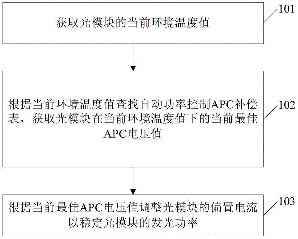
[0021] figure 1 A flowchart of an embodiment of the method for stabilizing the luminous power of the optical module provided by the present invention, such as figure 1 shown, including:

[0022] 101. Obtain the current ambient temperature value of the optical module.

[0023] The executor of the method for stabilizing the luminous power of...


PUM


Abstract

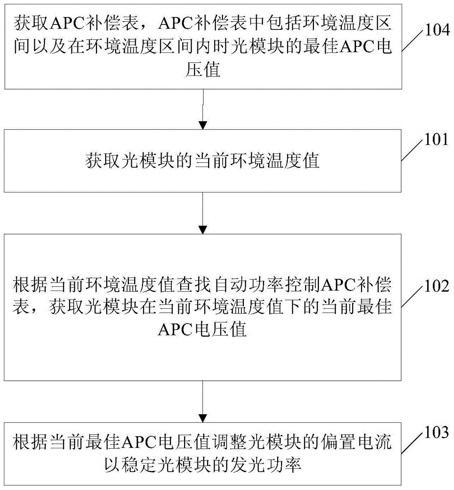
The invention relates to a method and a device for stabilizing the luminous power of an optical module. The method comprises the following steps of acquiring the current environmental temperature value of the optical module; searching an automatic power control (APC) compensation table according to the current environmental temperature value and acquiring the current optimal APC voltage value of the optical module under the current environmental temperature value; adjusting the bias current of the optical module according to the current optimal APC voltage value, so that when the luminous power of the optical module is changed due to rapid temperature change or high temperature, the bias current of the optical module can be directly adjusted according to the current optimal APC voltage value under the current environmental temperature value, the bias current of the optical module is adjusted to the current optimal bias current under the current environmental temperature value, the luminous power of the optical module can be stabilized according to the current optimal bias current, the influence of temperature on the optical module is reduced, and the light transmission performance of the optical module is improved.

Description

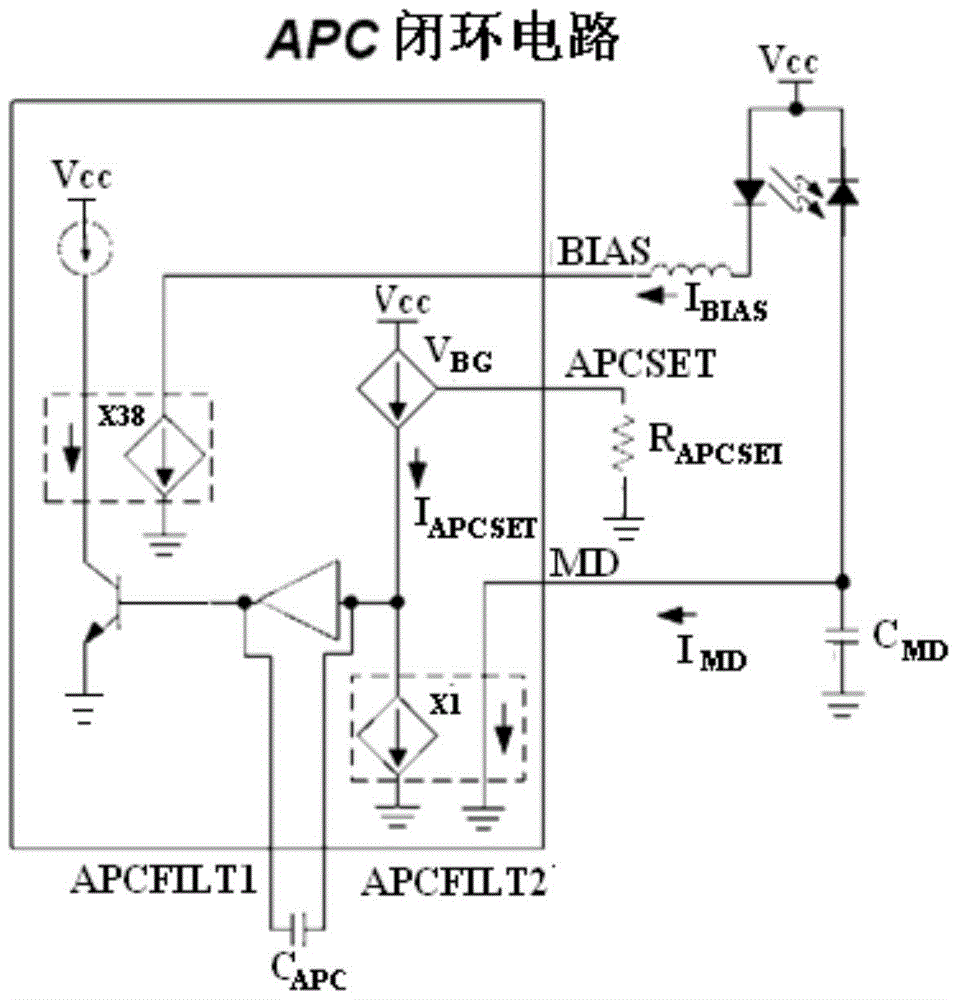
technical field [0001] The invention relates to the field of optoelectronic technology, in particular to a method and device for stabilizing the luminous power of an optical module. Background technique [0002] In the prior art, an optical module is a main component of an optical transmission device. The optical module includes a laser (LaserDiode, LD), a back photodetector (photoelectricity diode, PD), a driving circuit and a control unit MCU, etc. Due to the characteristics of the laser itself, the luminous efficiency of the optical module changes as the temperature changes. Especially at high temperature, the luminous efficiency of the optical module will decrease sharply, which affects the optical transmission performance of the optical module. [0003] In the prior art, when the laser works in the normal temperature range, if the luminous power changes, the monitoring current I back to the photodetector MD will change, the automatic power control (automatic power con...

Claims


Application Information

Patent Timeline
Patent Type & Authority Patents(China)
IPC IPC(8): H01S5/068
Inventor 崔涛
Owner HISENSE BROADBAND MULTIMEDIA TECH
Learn More