Feedback type automatic power control system

A technology of automatic power control and control unit, applied in the direction of control/adjustment system, lighting device, light source, etc., which can solve the problems of poor light directivity of LED 15, easy error and inconvenience in the control of luminous power, etc.

Inactive Publication Date: 2009-08-12
NATIONAL CHI NAN UNIVERSITY
View PDF1 Cites 0 Cited by
  • Summary
  • Abstract
  • Description
  • Claims
  • Application Information

AI Technical Summary

Problems solved by technology

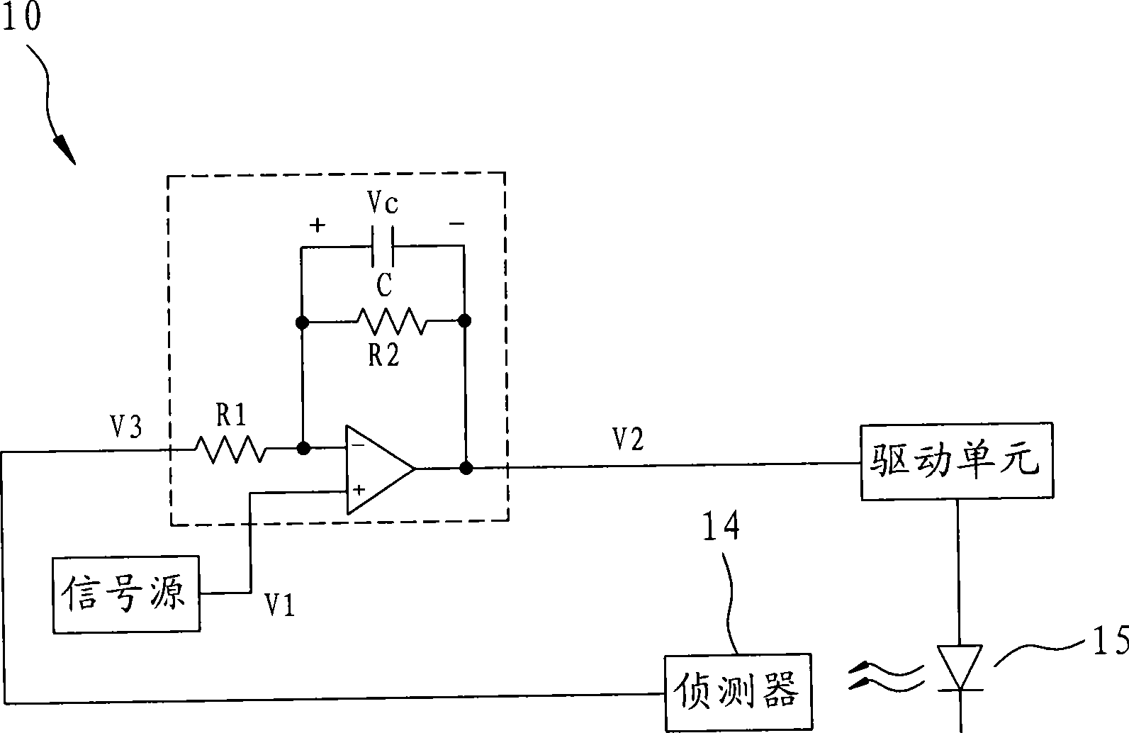
[0004] However, due to the poor directivity of the output light of the light emitting diode 15, the distance between the light detector 14 and the light emitting diode 15, the position, the light pollution of the environment, and the sensitivity of the light detector 14 will all have an impact on the detection signal. , so it is easy to have errors in the control of the luminous power. In addition, the detection signals output by the light detector 14 to the light emitting diode 15 with different wavelengths are also different. The light emitting diode 15 and the light detector 14 When matching different models, the control effect of the luminous power will be affected, so the above reasons will make it difficult to maintain the luminous power of the light emitting diode 15 stably with the current technology of the photodetector 14, resulting in poor results.
[0005] It can be seen that the above-mentioned existing automatic power control system obviously still has inconvenience and defects in structure and use, and needs to be further improved urgently.
In order to solve the above-mentioned problems, the relevant manufacturers have tried their best to find a solution, but for a long time no suitable design has been developed, and the general product has no suitable structure to solve the above-mentioned problems. This is obviously the relevant industry. Urgent problem

Method used


Image

  • Feedback type automatic power control system
  • Feedback type automatic power control system
  • Feedback type automatic power control system

Examples


Embodiment Construction

[0024] In order to further explain the technical means and effects of the present invention to achieve the intended purpose of the invention, the specific implementation, structure, and features of the feedback-type automatic power control system proposed according to the present invention will be described below in conjunction with the accompanying drawings and preferred embodiments. And its effect, detailed description is as follows.

[0025] The aforementioned and other technical contents, features and effects of the present invention will be clearly presented in the following detailed description of preferred embodiments with reference to the drawings. Through the description of the specific implementation mode, when the technical means and functions adopted by the present invention to achieve the predetermined purpose can be obtained a deeper and more specific understanding, but the accompanying drawings are only for reference and description, and are not used to explain t...


PUM


Abstract

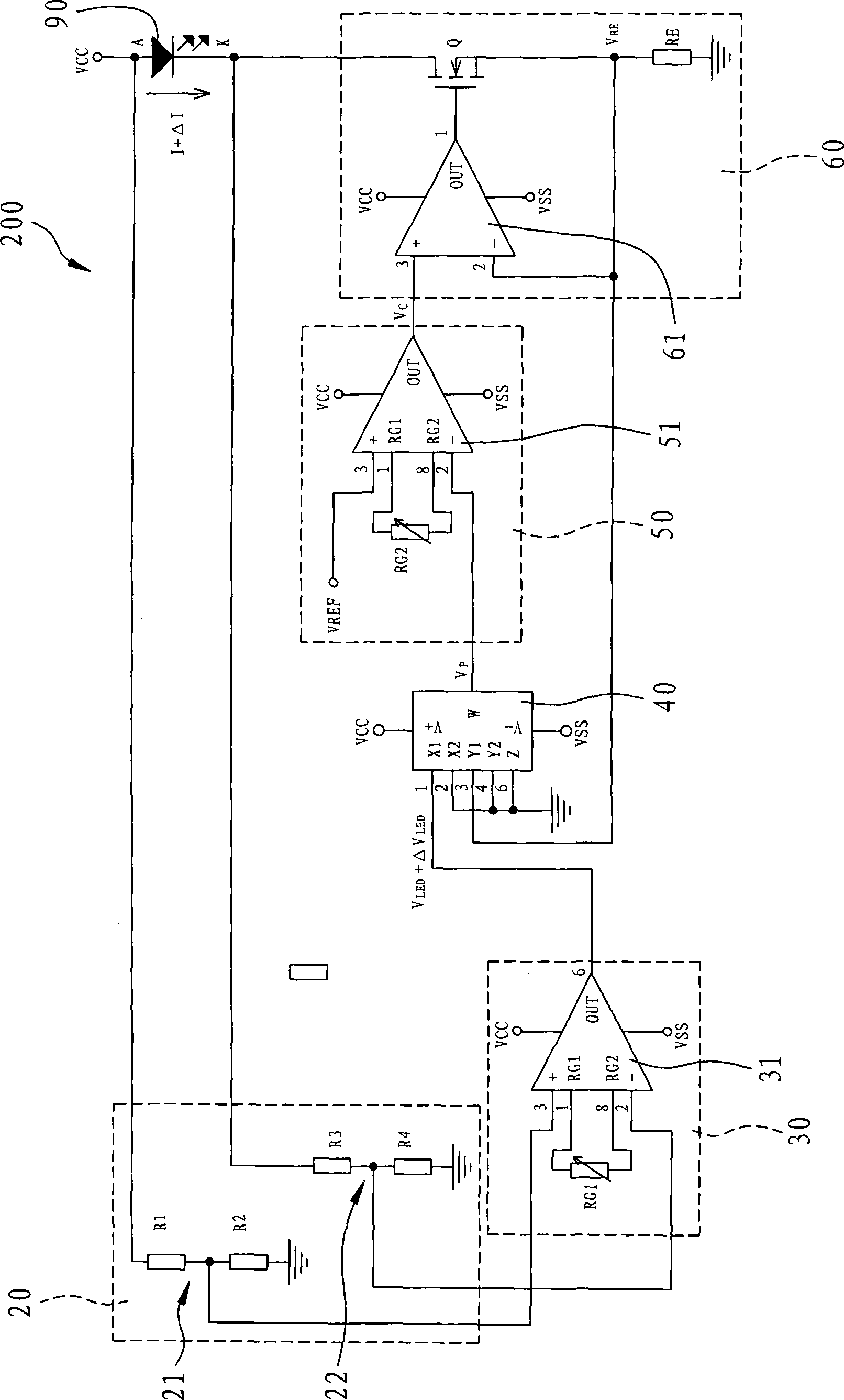
The invention relates to a feedback automatic power control system, which is suitable for controlling an electronic element, wherein the electronic element comprises two electrodes; the system comprises a multiplication unit, a control unit and an adjusting unit, wherein the multiplication unit outputs a measurement voltage value corresponding to the power of the electronic element by multiplying a working voltage value corresponding to the voltage difference of the two electrodes and a feedback voltage value corresponding to working current of the electronic element; the control unit outputs a control voltage corresponding to difference value change of the measured voltage value and a set voltage value; and the adjusting unit is electrically connected between the electronic element and the control unit and comprises a transistor connected in series with the electronic element, and the working state of the transistor is changed along with the control voltage of the control unit. The system can acquire the consumed power of the electronic element accurately, automatically adjust electricity supply for the electronic element by the control unit and the adjusting unit according to the consumed power change, and effectively realize the function of maintaining stability of the luminous power.

Description

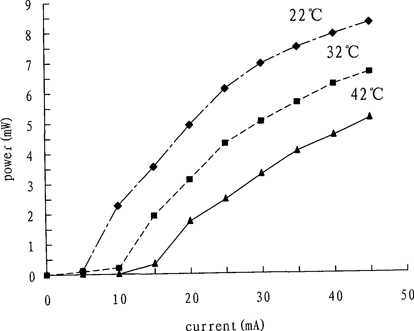
technical field [0001] The present invention relates to a power control system, in particular to a system that can accurately obtain the power consumption of electronic components, and then automatically adjust the power supply to electronic components through a control unit and an adjustment unit according to changes in power consumption, which can effectively maintain stable luminous power Functional feedback type automatic power control system. Background technique [0002] see figure 1 Shown is a graph illustrating the relationship between the luminous power and the operating current of a light-emitting diode at different element temperatures. When semiconductor elements such as light-emitting diodes and laser diodes are in operation, the luminous power will decrease as the temperature of the elements rises. Therefore, when light-emitting diodes are used without power control, the luminous power is likely to be unstable. [0003] see figure 2 As shown, it is a schema...

Claims


Application Information

Patent Timeline
Patent Type & Authority Applications(China)
IPC IPC(8): H05B37/02G05F1/10
Inventor 孙台平王嘉弘郑为修
Owner NATIONAL CHI NAN UNIVERSITY
Why Eureka
Try Eureka