
Ground light source calibration equipment of low-light cloud picture imaging instrument and calibration method of equipment

An imager and cloud image technology, applied in the field of remote sensing, can solve the problems of lack of isotropy, unstable light source luminous power, and difficult measurement of spectral characteristics, etc., to achieve good isotropy, stable luminous power, ensure uniformity and The effect of stability

Active Publication Date: 2016-11-16
PLA UNIV OF SCI & TECH
View PDF4 Cites 0 Cited by
  • Summary
  • Abstract
  • Description
  • Claims
  • Application Information

AI Technical Summary

Problems solved by technology

However, due to the unstable luminous power of the existing light source, the difficulty in measuring the spectral characteristics, and the lack of isotropy (Cao C.andY.Bai, 2014: Quantitative Analysis of VIIRS DNB Nightlight Point Source for Light Power Estimation and Stability Monitoring.Remote Sens.,6,11915-11935.doi:10.3390 / rs61211915.), the alternative calibration method based on the existing light source is still in the exploration stage, and there is no ground light source specially used as an alternative calibration source at home and abroad.

Method used


Image

  • Ground light source calibration equipment of low-light cloud picture imaging instrument and calibration method of equipment
  • Ground light source calibration equipment of low-light cloud picture imaging instrument and calibration method of equipment
  • Ground light source calibration equipment of low-light cloud picture imaging instrument and calibration method of equipment

Examples


Embodiment 1

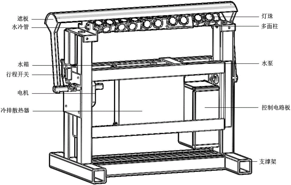
[0039] In this embodiment, the ground light source calibration equipment of the low-light nephogram imager mainly adopts the following components:

[0040] 1. The multi-faceted column in the light source unit is composed of 5 cuboids of 150*46*46mm. There is an 18-degree inclination between two adjacent cuboids. The 5 cuboids are equivalent to a 20-face column. The through hole in the middle of the multi-faceted column carries the cooling liquid . The lamp beads use 34 LED module lamp beads, the spectral range is 620-630nm, and the rated power of a single lamp bead is 100W.

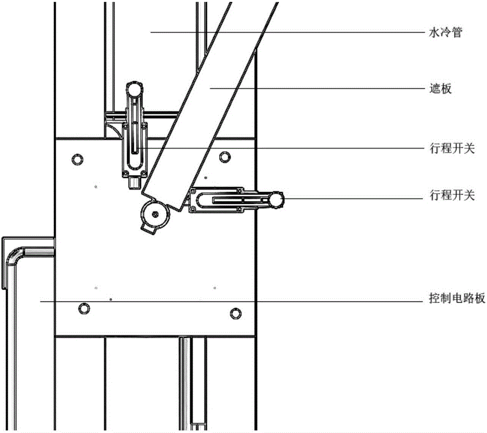
[0041]2. The control circuit in the control unit adopts double-sided PCB board, selects ATxmega, LM2596, AMS1117 and other components, and controls the rotation and stop of the motor and the operation and shutdown of the whole equipment through programming. The travel switch adopts the self-resetting adjustable roller arm type, and the contacts are one normally open and one normally closed. The control ...


PUM


Abstract

The invention discloses ground light source calibration equipment of a low-light cloud picture imaging instrument and a calibration method of the equipment. The equipment comprises a supporting unit, a light source unit, a control unit and a heat dissipating unit. The supporting unit is used for supporting other units. The light source unit comprises a polygonal column and 34 light beads, and is used for providing upstream radiation with irradiance uniformly distributed. The control unit comprises a control circuit board, a travel switch, a motor and a sheltering plate, wherein the control circuit board drives the travel switch to trigger rotation and stoppage of the motor, the motor drives the sheltering plate to ascend or descend, and the sheltering plate is located above the light source unit when ascending. A water pump in the heat dissipating unit drives heat dissipating liquid to circularly flow among a cold-discharging heat dissipating device, a water tank and a water cooling pipe to dissipate heat for the whole equipment. Parameters such as the irradiance of a light source, the atmosphere profile and moonlight spectra are input into a radiation transfer mode to simulate the pupil entrance radiance of the atmosphere top low-light cloud picture imaging instrument, DN values measured by sensors are compared, and thus vicarious calibration of the low-light cloud picture imaging instrument with the ground light source is achieved.

Description

technical field [0001] The invention belongs to the technical field of remote sensing, in particular to a ground light source calibration device and a method for a low-light cloud imager. Background technique [0002] At present, the best way to achieve nighttime low-light radiometric calibration is site substitution calibration based on radiative transfer simulation. Deserts, ice sheets, and deep convective clouds with high reflectivity and stable surface properties are often used as alternative calibration target areas. These three alternative calibration methods are all based on the basic condition of the reflection of the moonlight by the ground or deep convective clouds, and the lunar radiation model needs to be introduced as the input of the radiation transfer model (Ma Shuo, Huang Yunxian, Yan Wei, Ai Weihua, Zhao Xianbin) . Calibration technology of nighttime low-light sensor based on deep convective cloud [J]. Journal of Infrared and Millimeter Wave, 2015, 34(5): 63...

Claims


Application Information

Patent Timeline
IPC IPC(8): G01C25/00
CPCG01C25/00
Inventor 胡申森翟东力严卫马烁黄云仙江军戈书睿孙睿安豪王蕊王迎强陆文
Owner PLA UNIV OF SCI & TECH
Learn More