A fuel droplet ignition temperature measurement device for visualization experiments

A temperature measuring device and experimental technology, applied in the direction of measuring devices, combustion and ignition, and electric devices, etc., can solve the problems of not being able to observe the relevant parameters of the sample projection status, resistance wires affecting the effect of observation, and affecting the accuracy of experimental results, etc. To achieve the effect of ensuring uniform stability, high stability and reducing influence

Active Publication Date: 2021-01-05
ANHUI UNIVERSITY OF TECHNOLOGY
View PDF9 Cites 0 Cited by
  • Summary
  • Abstract
  • Description
  • Claims
  • Application Information

AI Technical Summary

Problems solved by technology

[0004] For example, the Chinese patent application number is 201110110037.6, and the name of the invention is: new experimental ignition device. The device in this application also uses electric ignition to ignite high-energy fuel, but the research object of this device is relatively single, only solid high-energy fuel, and Although the ignition means of this device is electric heating, the controllability of the heating temperature is low. For the situation that the heating temperature may change under different experimental conditions, the temperature control is troublesome, which affects the accuracy of the experimental results.
In addition, the application with the patent number ZL99245415.8 discloses a new type of tube-type high-temperature furnace, but the resistance wire will affect the observation effect during the electric heating process using the device of the application, and the projection status of the samples in the furnace cannot be observed. And the relevant parameters of the synchronization test

Method used


Image

  • A fuel droplet ignition temperature measurement device for visualization experiments
  • A fuel droplet ignition temperature measurement device for visualization experiments
  • A fuel droplet ignition temperature measurement device for visualization experiments

Examples


Embodiment 1

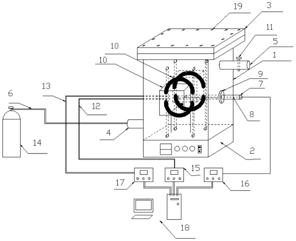
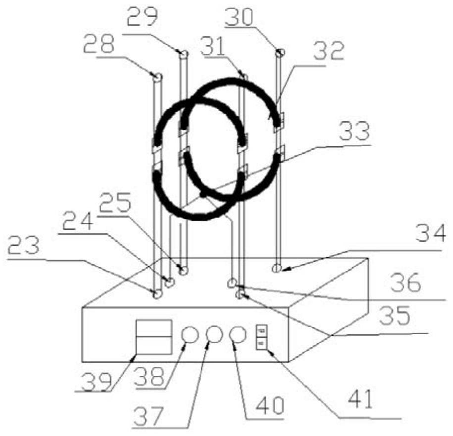
[0037] combine Figure 1-Figure 4 As shown, a fuel droplet ignition temperature measurement device for a visualization experiment in this embodiment includes a combustion chamber 1, a combustion sample pushing mechanism and a data collection and processing mechanism, and the fuel to be tested is pushed into the combustion chamber 1 through the combustion sample pushing mechanism Carry out the combustion test, and use the data acquisition and processing mechanism to collect, process and analyze the parameters of the fuel combustion process, such as smoke composition, pressure, temperature, etc. Wherein, the first ignition column 28, the second ignition column 31, the third ignition column 30 and the fourth ignition column 29 are provided with symmetrical distribution in the combustion chamber 1, and these four ignition columns surround and form a rectangular structure (located at the apex of the rectangle respectively). position), each ignition column is provided with two ignit...

Embodiment 2

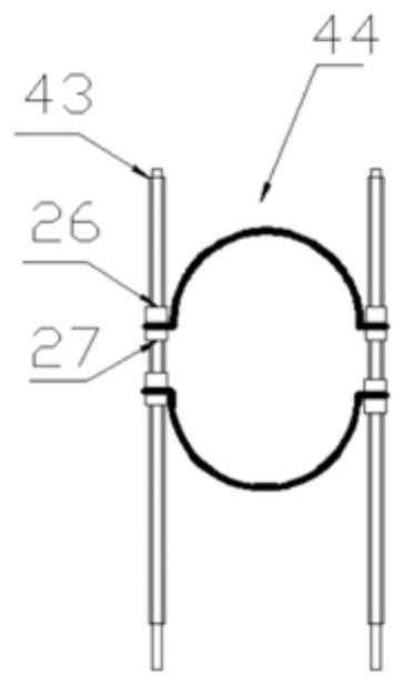
[0040] A fuel droplet ignition temperature measuring device for a visualization experiment of the present embodiment is basically the same in structure as that of Embodiment 1, and its difference mainly lies in: combining Figure 1-Figure 3 , the ignition column in this embodiment is made of stainless steel, and the area above the upper ignition wire fastening device, the area below the lower ignition wire fastening device and the area between the two fastening devices on each ignition column are all set There is a detachable insulating ceramic cover 43, and the ignition column at the installation position of the ignition wire fastening device is in an exposed state (there is no ceramic cover 43). The above-mentioned ignition wire fastening device includes an upper rotating piece 26 and a lower rotating piece 27 that cooperate with each other, and the end of the arc-shaped ignition wire 32 is fastened to the bare part of the ignition column through the fastening device. like ...

Embodiment 3

[0043] A fuel droplet ignition temperature measuring device for a visualization experiment of this embodiment is basically the same in structure as that of Embodiment 2, and the difference mainly lies in: Figure 4 As shown, the combustion sample pushing mechanism of this embodiment includes a sample pushing rod 7, a sealing plug 42 and a sealing ring 9. The inside of the sealing plug 42 is processed with a through hole for the sample pushing rod 7 to pass through. The sample pushing rod 7 is installed in the opening on one side of the combustion chamber 1 and sealed by the sealing ring 9, and the sample pushing rod 7 is provided with a slot at one end of the combustion chamber 1, through which the solid sample can be directly held, If the sample is liquid, hang it directly on the thermocouple, and put it in the slot as for the mixed sample.

[0044] Therefore, through the structural design of the combustion sample pushing mechanism, on the one hand, the combustion test requir...


PUM


Abstract

The invention discloses a fuel droplet ignition temperature measuring device for visible experiments and belongs to the technical field of combustion experiment equipment. According to the ignition temperature measuring device disclosed by the invention, four ignition columns in symmetric distribution are arranged in a combustion chamber; the four ignition columns encircle a rectangular structure;two ignition wire fastening devices distributed at an interval are arranged on each ignition column; four arc-shaped ignition wires in symmetric distribution are mounted among the four ignition columns through the ignition wire fastening devices in a fastened manner; a through hole through which a combustion sample push mechanism penetrates is formed in one side of the combustion chamber; the push direction of the combustion sample push mechanism is parallel to the plane of the arc-shaped ignition wire and is along the central line of the four arc-shaped ignition wires. By adopting the devicedisclosed by the invention, an ignition process has good stability, the device can be repeatedly used for multiple times according to demands, high stability can be effectively maintained in a repeated use process, and precision of experiment results can be ensured.

Description

technical field [0001] The invention belongs to the technical field of combustion experiment equipment, and more specifically relates to a visualization device applied to the research on fuel solid, liquid and solid-liquid mixed combustion mechanism. Background technique [0002] With the continuous development of new energy sources, a variety of high-energy fuels have appeared, and their phases also have a variety of states. The ignition process of high-energy fuels is of great significance for their application in combustion and propulsion and for revealing the combustion mechanism of high-energy fuels. At present, the ignition methods used in the research of high-energy fuel combustion mainly include: chemical ignition, gunpowder ignition, laser ignition and electric ignition. Among them, using chemical ignition, the device is more complicated, there are many components, and it is not conducive to simplifying the system, and the use of igniter needs to select the appropri...

Claims


Application Information

Patent Timeline
Patent Type & Authority Patents(China)
IPC IPC(8): G01N31/12G01K7/02F23Q7/00
CPCF23Q7/00G01K7/02G01N31/12
Inventor 孙运兰韩伟康朱宝忠石伟陈颖何成雨
Owner ANHUI UNIVERSITY OF TECHNOLOGY
Why Eureka
Try Eureka