
Laser semiconductor material evidence discovery device based on apc and constant temperature intelligent control

An intelligent control, semiconductor technology, applied in temperature control, optical device exploration, temperature control by electric means, etc., can solve the problems of inability to meet the fluorescence display of excited physical evidence, power increase, and difficulty in meeting the laser low temperature working environment, etc. The effect of preventing laser wavelength drift and preventing personal injury

Active Publication Date: 2020-04-21
广东腾德同普科技股份有限公司
View PDF6 Cites 0 Cited by
  • Summary
  • Abstract
  • Description
  • Claims
  • Application Information

AI Technical Summary

Problems solved by technology

[0002] In the existing laser discovery equipment, the PD in the laser semiconductor is used as a reference voltage. With the increase of the laser output power emitted by the LD, the indoor temperature of the laser discovery equipment increases accordingly. Since the laser is very sensitive to temperature, the power is constantly increasing. The stability of the laser light emission cannot be guaranteed; the existing portable laser discovery equipment only adopts simple active heat dissipation forms such as fans, which is difficult to meet the low temperature working environment of the laser, and thus the laser spectral wavelength of the light output varies with the temperature Drift occurs due to the increase of temperature, which cannot satisfy the fluorescence display of exciting physical evidence; for example, the conventional laser spectrum with a wavelength of 445nm can be used to excite biological evidence of sweat traces, but as the temperature increases, the wavelength will continue to increase. At this wavelength, it will be difficult to show the biological evidence of sweat traces well

Method used


Image

  • Laser semiconductor material evidence discovery device based on apc and constant temperature intelligent control
  • Laser semiconductor material evidence discovery device based on apc and constant temperature intelligent control
  • Laser semiconductor material evidence discovery device based on apc and constant temperature intelligent control

Examples


Embodiment 1

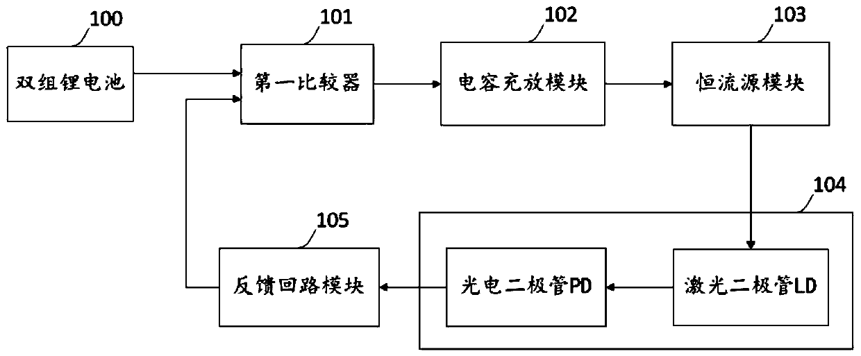
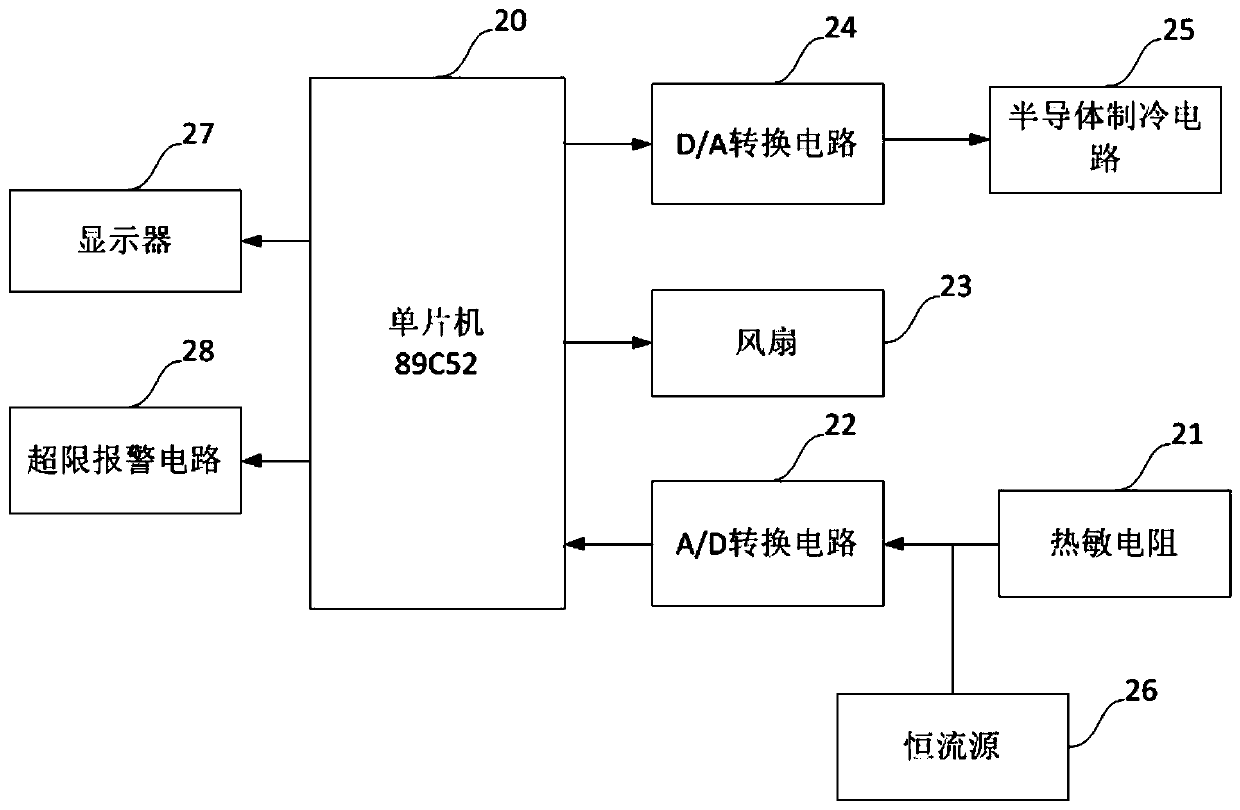
[0038] see figure 1 , a laser semiconductor evidence discovery device based on APC and constant temperature intelligent control, including a coaxial line L distributed and sequentially socketed optical lens combination structure, a heat dissipation mechanism, a control system compartment 13 and an aluminum battery installation compartment 14, the aluminum battery Double sets of lithium batteries 17 are placed inside the installation compartment 14, and an aluminum battery installation compartment sealing cover 15 is arranged at the rear, and a switch 16 for providing power on and off for the physical evidence discovery device is arranged on the aluminum battery installation compartment 14; The multi-channel output drive control system 3 and the fan 23 for heat dissipation are also arranged on the axis L in the warehouse; The back end of the semiconductor 104 is provided with a semiconductor cooler 2 (Thermo Electric Cooler, hereinafter referred to as TEC), and the temperature ...

Embodiment 2

[0051] This embodiment is based on embodiment 1, the difference is that, see Figure 4 , in the automatic power control APC driving circuit, the constant current source module 103 includes a first operational amplifier A1 (model LT1006), a second operational amplifier A2 (model LT1789), a first triode Q1, a second triode Q2, a first A diode D1, a second diode D2, a first resistor R1, a second resistor R2, a third resistor R3, a fourth resistor R4, a fifth resistor R5, a first capacitor C1 and a Zener diode DW1;

[0052] The first operational amplifier A1, its non-inverting input end is connected to the output end of the capacitor charging and discharging module 102 as the input end of the constant current source module 103, its inverting input end is connected to the first end of the first capacitor C1, the first capacitor C1 The second terminal is connected to the output terminal of the first operational amplifier A1, and its output terminal is connected to the control termin...

Embodiment 3

[0073] This embodiment is based on embodiment 1, the difference is that, see Image 6 , the multi-channel output drive control system also includes a slow-start fading drive circuit 300', which is used to prevent misoperation from starting the laser diode to emit light instantly,

[0074] The slow-start fading drive circuit 300' is arranged between the double-set lithium battery 100 and the first comparator 101, the output end of the double-set lithium battery 100 is connected to the input end of the slow-start fade-on drive circuit 300', and the slow-start fade-on drive The output terminal of the circuit 300 ′ is connected to the input terminal of the first comparator 101 .

[0075] Laser semiconductors often generate a huge inrush current at the moment of startup and shutdown, which is enough to damage the laser semiconductor. At the same time, because the light source excited by the laser semiconductor has certain damage to the human body, the moment of startup may be due t...


PUM


Abstract

The invention discloses a laser semiconductor evidence discovery device based on APC and constant temperature intelligent control. Set up a multi-channel output drive control system, which includes an automatic power control drive circuit for outputting stable light and an intelligent constant temperature control semiconductor refrigerator circuit for preventing laser wavelength drift. The present invention is based on the APC and constant temperature intelligent control of the laser semiconductor material evidence discovery device, which outputs stable luminous power and has a laser semiconductor working environment that prevents laser wavelength drift.

Description

technical field [0001] The invention relates to the technical field of photoelectric instruments, in particular to a laser semiconductor evidence discovery device based on APC and constant temperature intelligent control. Background technique [0002] In the existing laser discovery equipment, the PD in the laser semiconductor is used as a reference voltage. With the increase of the laser output power emitted by the LD, the indoor temperature of the laser discovery equipment will increase accordingly. Since the laser is very sensitive to temperature, the power will continue to increase. The stability of the laser light emission cannot be guaranteed; the existing portable laser discovery equipment only adopts simple active heat dissipation forms such as fans, which is difficult to meet the low temperature working environment of the laser, and thus the laser spectral wavelength of the light output varies with the temperature Drift occurs due to the increase of temperature, whi...

Claims


Application Information

Patent Timeline
Patent Type & Authority Patents(China)
IPC IPC(8): G05D23/24G05D23/30G05F1/66H03K17/28G01N21/64G01V8/10H05B33/08H05B44/00
CPCH03K17/28G05D23/24G05D23/303G05F1/66G01N21/6402G01N21/6428G01V8/10G01N2021/6439H05B45/20H05B45/37
Inventor 李振琦
Owner 广东腾德同普科技股份有限公司
Learn More