
Water dispenser with cup supporting plate lifting mechanism

The technology of a lifting mechanism and a water dispenser is applied to beverage preparation devices, household appliances, applications, etc., and can solve the problems of tea losing good taste, affecting use, and inconvenience to users.

Active Publication Date: 2014-04-09
深圳市北鼎晶辉科技有限公司
View PDF8 Cites 24 Cited by
  • Summary
  • Abstract
  • Description
  • Claims
  • Application Information

AI Technical Summary

Problems solved by technology

[0002] In the traditional water dispenser, the cup tray of the water dispenser is fixed. The general method of use is to put the teacup on the cup tray, press the button to start boiling water, and the water dispenser will start to work. When the water is boiled When the temperature is set, the water dispenser will automatically put the boiled water into the cup. In order to adapt to the water cups of different heights, the water outlet of this water dispenser is set at a relatively high position. For small cups, the hot water from the drinking water There is a certain distance from the water outlet of the machine to the water cup, especially in winter, after the hot water passes through such a long distance, it will be cooled, so that the temperature of the water that has been boiled to the set temperature will be reduced. If this water is used to make tea , the brewed tea will lose its proper taste, and the hot water may splash out of the cup, which brings great inconvenience to the user
However, if the water outlet is set at a lower position, the higher cup cannot be put in, which will affect the use

Method used


Image

  • Water dispenser with cup supporting plate lifting mechanism
  • Water dispenser with cup supporting plate lifting mechanism
  • Water dispenser with cup supporting plate lifting mechanism

Examples


Embodiment Construction

[0020] Below in conjunction with embodiment the present invention is further described.

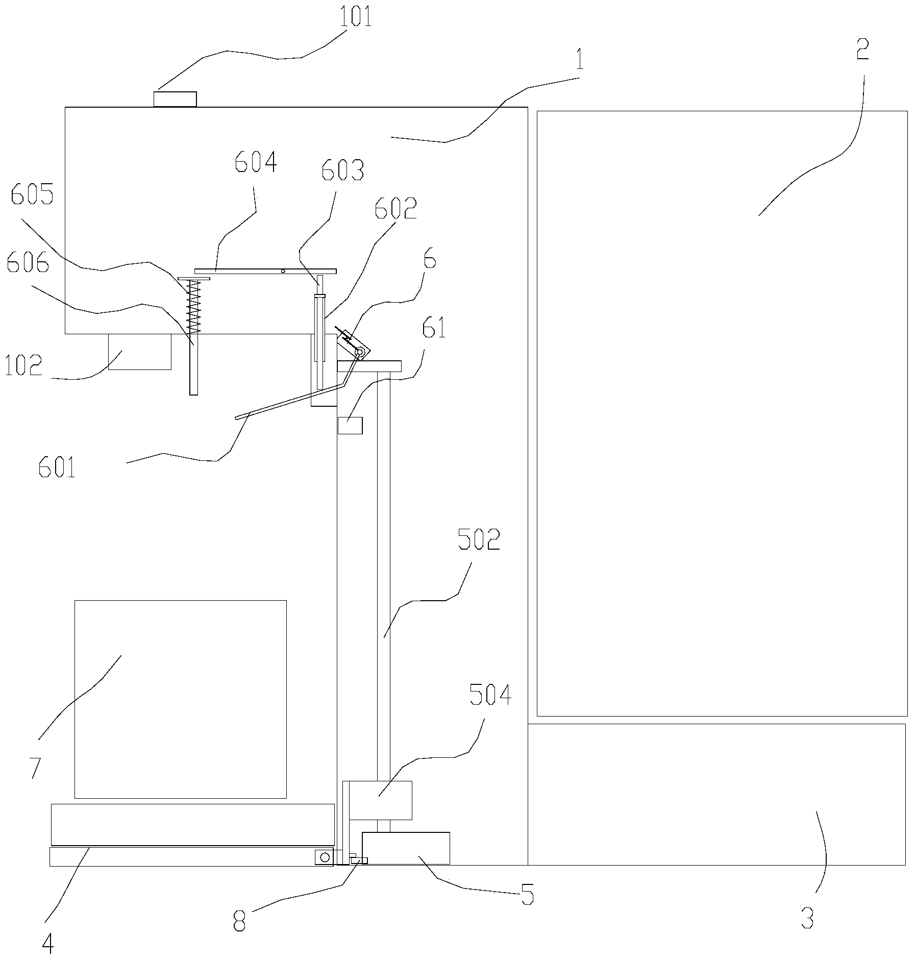
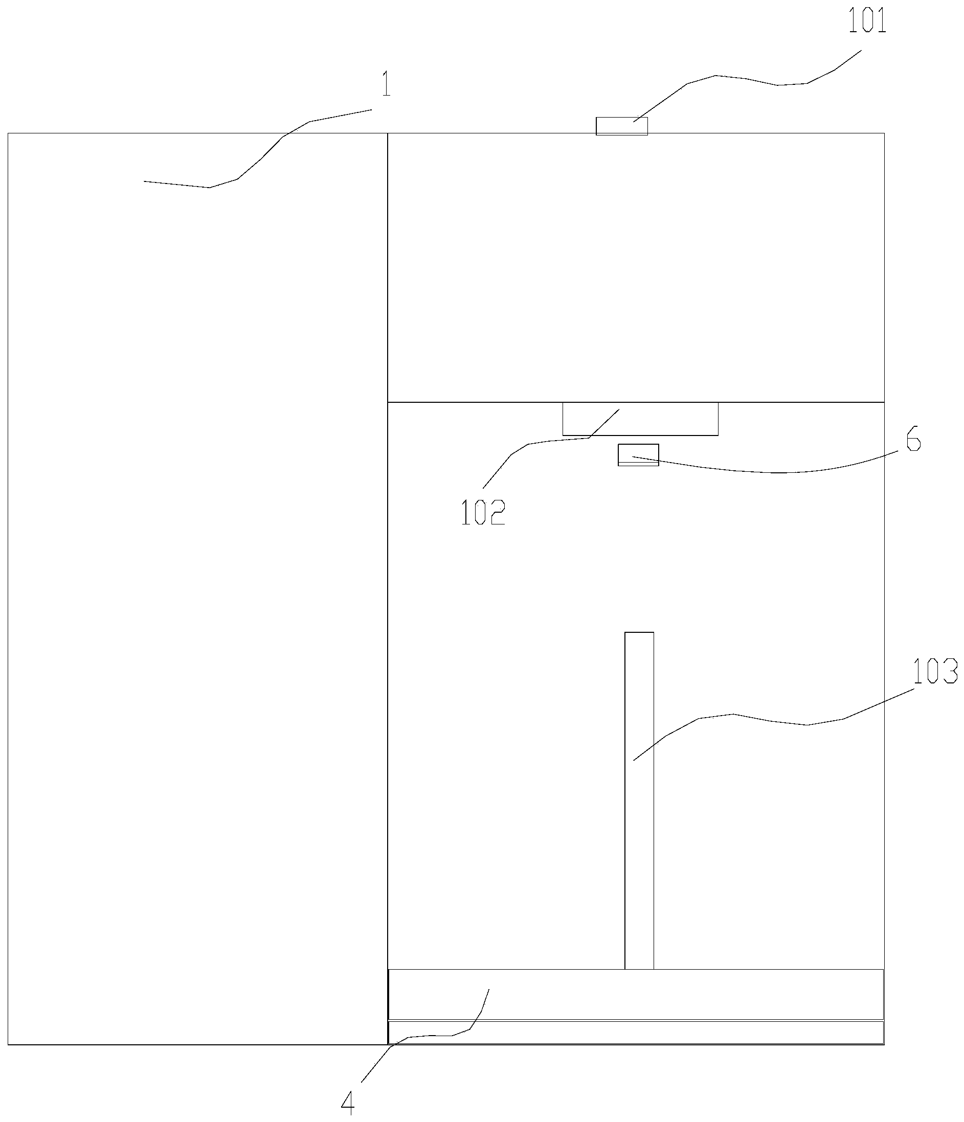
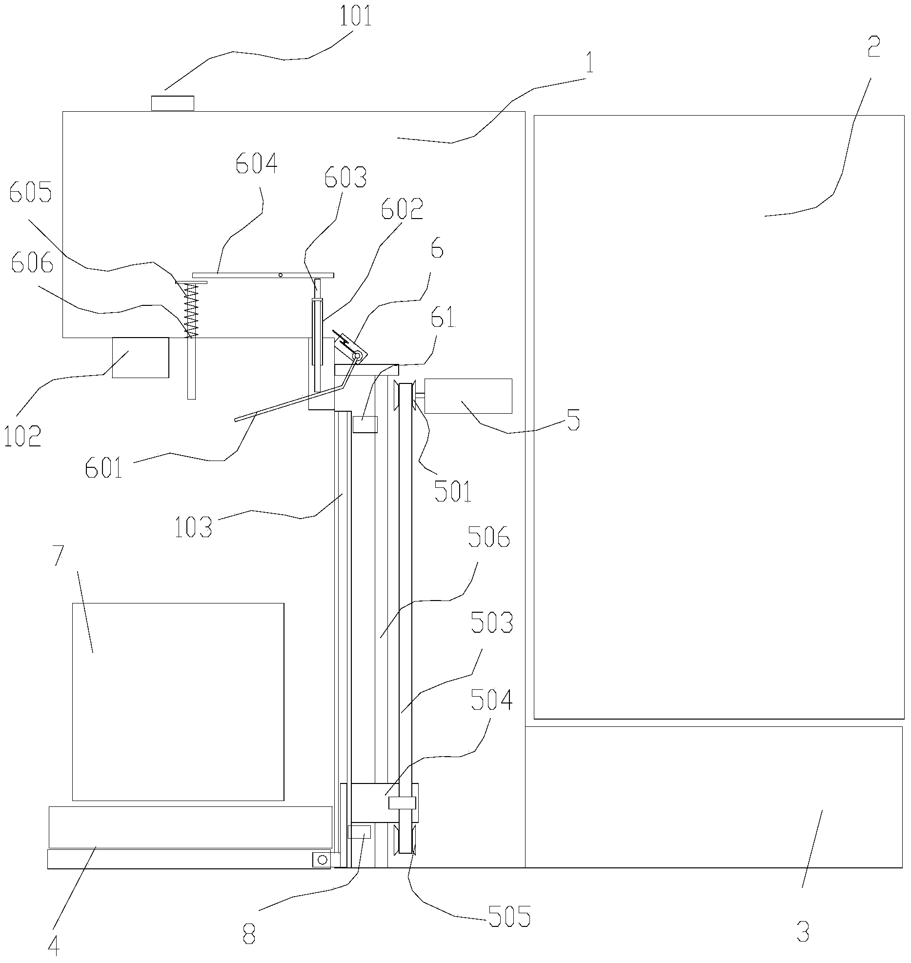
[0021] Such as figure 1 , figure 2 As shown, a water dispenser provided with a lifting mechanism for cup trays includes a machine base 1, a water tank 2, a base 3, a cup tray 4, a water cup 7 and a control circuit, the water tank 2 is arranged on the base 3, and the The base 1 is provided with a chute 103, a cup tray 4 slidingly connected with the chute 103, a cup tray drive mechanism, a water level detection device, an upper limit switch 6 and a lower limit switch 8; the upper limit switch 6 and the lower limit switch 8 are respectively fixed on the support 1, and are in the upper and lower limit positions of the stroke track of the carriage 504; 502 rotating motor 5, one end of the screw rod 502 is movably connected with the base 1, and the other end is connected with the output shaft of the motor 5, the motor 5 is fixed on the base 1, and the carriage 504 is hinged with a support cu...


PUM


Abstract

The invention discloses a water dispenser with a cup supporting plate lifting mechanism and relates to water dispensers. The water dispenser comprises a water dispenser seat (1), a water tank (2), a base (3) and a cup supporting plate (4). The water tank (2) is arranged on the base (3), the water dispenser seat (1) is provided with a sliding groove (103), the cup supporting plate (4) connected with the sliding groove (103) in a sliding mode and a cup supporting plate drive mechanism. The cup supporting plate (4) drive mechanism is arranged in rear of the sliding groove (103), and the cup supporting plate (4) penetrates through the sliding groove (103) and is connected with a sliding frame (504) arranged in the cup supporting plate drive mechanism. A power transmission mechanism of the cup supporting plate drive mechanism drives the sliding frame (504) to move in the limiting direction of the sliding groove (103). According to the water dispenser with the cup supporting plate lifting mechanism, a cup can be automatically lifted to a water outlet of the water dispenser and stop according to the height of the cup, it is ensured that the cup receives hot water at the position closest to the hot water outlet in spite of the height of the cup, and the problems that the temperature of hot water is affected and the hot water is splashed due to different heights of water cups are effectively solved.

Description

technical field [0001] The present invention relates to water dispensers. Background technique [0002] In the traditional water dispenser, the cup tray of the water dispenser is fixed. The general method of use is to put the teacup on the cup tray, press the button to start boiling water, and the water dispenser will start to work. When the water is boiled When the temperature is set, the water dispenser will automatically put the boiled water into the cup. In order to adapt to the water cups of different heights, the water outlet of this water dispenser is set at a relatively high position. For small cups, the hot water from the drinking water There is a certain distance from the water outlet of the machine to the water cup, especially in winter, after the hot water passes through such a long distance, it will be cooled, so that the temperature of the water that has been boiled to the set temperature will be reduced. If this water is used to make tea , will make the brewe...

Claims


Application Information

Patent Timeline
IPC IPC(8): A47J31/44
Inventor 张默晗陈华金黄继峰
Owner 深圳市北鼎晶辉科技有限公司
Learn More