
Dental filling machine

A dental filling device and cylinder technology, which is applied in dentistry, tooth filling, dental prosthetics, etc., can solve the problems of frequent tool changes, and achieve the effect of saving operation time, convenient operation, and time saving

Inactive Publication Date: 2014-04-09
宋伟
View PDF5 Cites 1 Cited by
  • Summary
  • Abstract
  • Description
  • Claims
  • Application Information

AI Technical Summary

Problems solved by technology

In the present invention, a heating component is provided, and the heating component is used to heat the filling material to keep the temperature of the filling material so that it is always suitable for filling the teeth, so that the dentist can focus on filling the teeth without worrying about the solidification of the filling material. A bendable needle is set in the center for shape modification, which solves the problem that dentists need to change tools frequently and saves operation time

Method used


Image

  • Dental filling machine

Examples


Embodiment 1

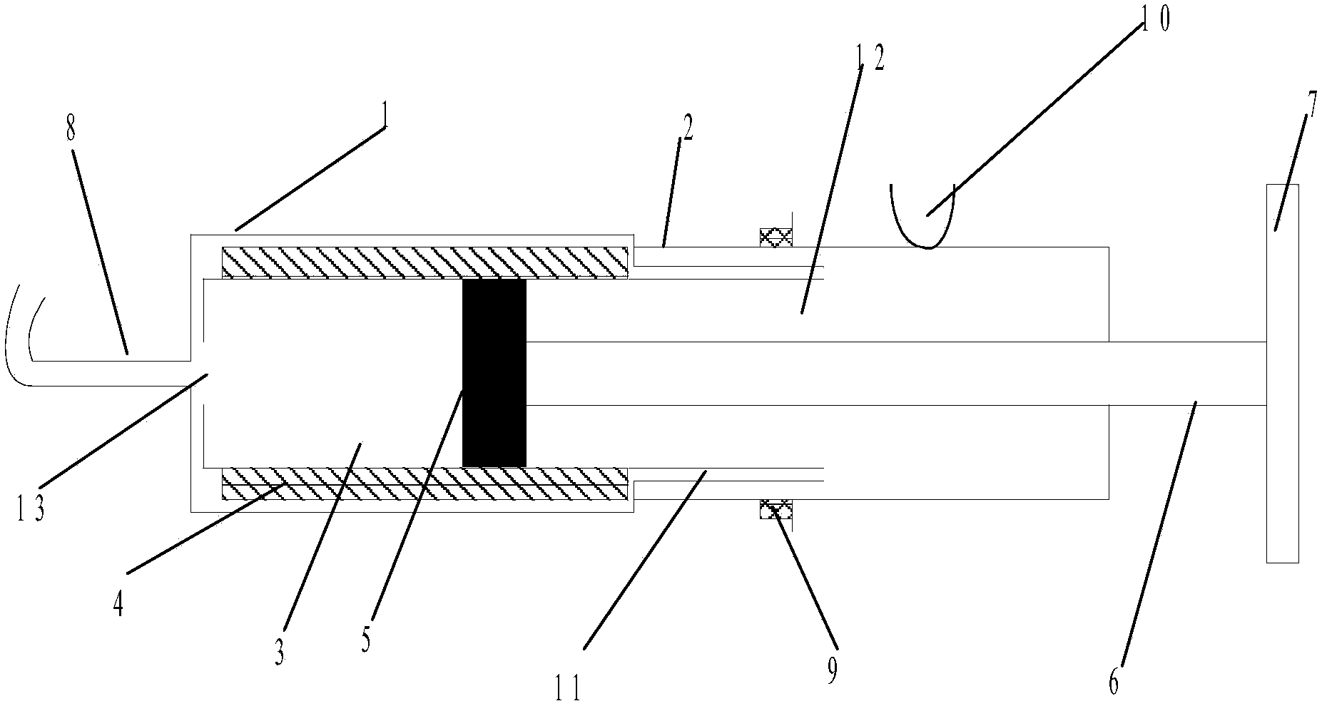
[0026] Such as figure 1 As shown, the present invention provides a dental plug, comprising:

[0027] A cylinder, which includes a first cylinder 1 and a second cylinder 2, the first end of the first cylinder 1 is provided with a needle 8, and the second end of the first cylinder 1 is sleeved on the second cylinder The first end of the second barrel 1; the needle 8 is made of memory metal material, the needle end of the needle 8 is flush, and the tail end of the needle 8 is connected to the first end of the first syringe 1 ; One side of the second cylinder 2 is provided with a slot 10, the slot 10 is U-shaped, and the slot 10 is used for clamping the hose of the teeth cleaning device.

[0028] Storage tank 3, which is arranged in the first cylinder body 1, the length of the storage tank 3 is less than 1 cm of the length of the first cylinder body 1, and the storage tank 3 has a filler inlet 12 and a filling material A material outlet 13, the filling material outlet 13 is arra...

Embodiment 2

[0036] Such as figure 1 As shown, the present invention provides a dental plug, comprising:

[0037] A cylinder, which includes a first cylinder 1 and a second cylinder 2, the first end of the first cylinder 1 is provided with a needle 8, and the second end of the first cylinder 1 is sleeved on the second cylinder The first end of the second barrel 1; the needle 8 is made of memory metal material, the needle end of the needle 8 is flush, and the tail end of the needle 8 is connected to the first end of the first syringe 1 ; One side of the second cylinder 2 is provided with a slot 10, the slot 10 is U-shaped, and the slot 10 is used for clamping the hose of the teeth cleaning device.

[0038] Storage tank 3, which is arranged in the first cylinder body 1, the length of the storage tank 3 is less than the length 3cm of the first cylinder body 1, the storage tank 3 has a filler inlet 12 and a filling material A material outlet 13, the filling material outlet 13 is arranged cor...


PUM

PropertyMeasurementUnit
Lengthaaaaaaaaaa

Abstract

The invention discloses a dental filling machine, comprising a barrel, a storage cylinder and a piston, wherein the barrel comprises a first barrel and a second barrel; a syringe needle is arranged at the first end of the first barrel; the second end of the first barrel is sleeved at the first end of the second barrel; the storage cylinder is arranged inside the first barrel and comprises a filling material inlet and a filling material outlet; the filling material outlet corresponds to the syringe needle; the filling material inlet extends into the second barrel; a space is formed between the storage cylinder and the first barrel and used for providing a heating component; the piston is arranged inside the storage cylinder; a main push rod main body and a push handle, which are used for applying pressure are sequentially arranged at one end of the piston; and the main push rod body extends out of the second end of the second barrel. The heating device is arranged inside the dental filling machine and used for heating the filling material to keep the temperature of the filling material, and meanwhile, the filling, repairing and cleaning in the tooth filling process are integrated, so that the dental filling machine is convenient and practical.

Description

technical field [0001] The present invention relates to a dental plug. Background technique [0002] In dental surgery, it is often necessary to fill in the missing part of the tooth, and then modify the filled material to restore the shape of the patient's tooth. The traditional filling tools for filling teeth, modifying tools and cleaning tools are all separated, and the stomatologist needs to replace the tools to complete the tooth filling operation. The operation is cumbersome and increases the workload of the doctor. At the same time, the traditional tools for filling teeth do not have heating devices, and doctors need to complete the filling within a fixed time. Unless skilled doctors, generally intern doctors operate slowly, and it is easy to waste filling materials, and due to rush, it is likely to cause filling Ineffective. Contents of the invention [0003] The invention designs and develops a dental filling device. In the present invention, a heating componen...

Claims


Application Information

Patent Timeline
IPC IPC(8): A61C5/04
Inventor 宋玮刘召萍张枫宋红薛新霞李富冯秀栓
Owner 宋伟
Learn More