Process for protecting a component, process for laser drilling and component

A technology for laser drilling and protecting components, which can be used in laser welding equipment, applications, household appliances, etc., and can solve problems such as cost

Inactive Publication Date: 2014-04-09
SIEMENS AG
View PDF16 Cites 4 Cited by
  • Summary
  • Abstract
  • Description
  • Claims
  • Application Information

AI Technical Summary

Problems solved by technology

Laser radiation is then carried out, wherein the material mus

Method used


Image

  • Process for protecting a component, process for laser drilling and component
  • Process for protecting a component, process for laser drilling and component
  • Process for protecting a component, process for laser drilling and component

Examples


Embodiment Construction

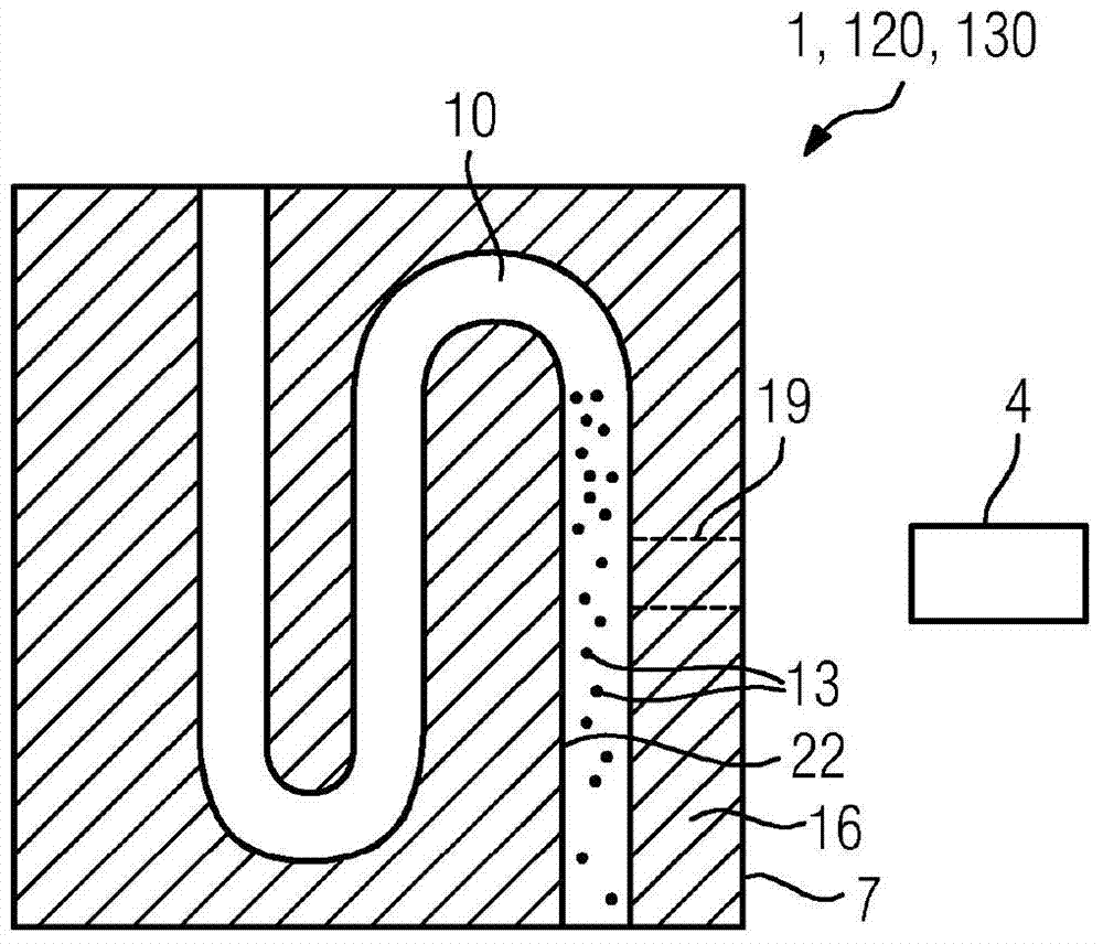
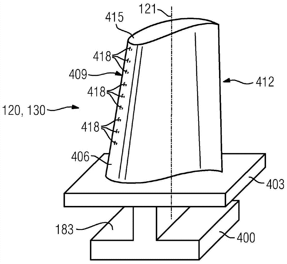
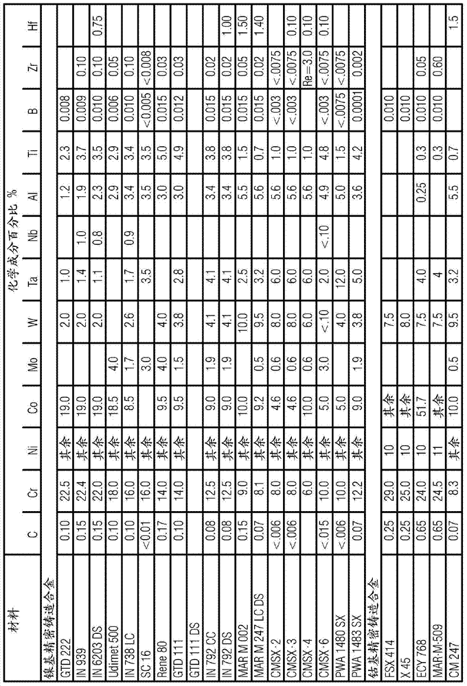
[0013] figure 1 The hollow component 1 shown only as an example is made of a nickel-based or cobalt-based alloy (preferably according to image 3 ) made of turbine blades 120, 130 ( figure 2 ), the hollow member has a cavity 10 . The wall 16 of the hollow space 10 of the component 1 , 120 , 130 is intended to pass through in particular—indicated by dashed lines—in a region 19 a through-opening 19 (described below only by way of example). This is done by means of a laser 4 (or an electron gun), whose beam removes material of the wall 16 from the surface 7 . During penetration into the cavity 10 , the inner structure 22 in the cavity 10 of the hollow component 1 , 120 , 130 can be damaged.

[0014] In order to avoid this, Teflon powder 13 is introduced into cavity 10 at least in the region of through-holes 19 to be produced. Here, Teflon powder 13 is introduced into cavity 10 via a carrier liquid. The above-mentioned carrier liquid is preferably water-based. Here, Teflon ...


PUM

PropertyMeasurementUnit
Concentrationaaaaaaaaaa
Granularityaaaaaaaaaa

Abstract

The cavity of a hollow component (1) is easily and rapidly filled with Teflon powder, and full protection of the internal structure (22) can be achieved. In addition, the filling material can be easily removed after laser drilling.

Description

technical field [0001] The invention relates to a method for laser drilling and a corresponding protection method as well as a component in which a filling material is introduced into the hollow component. Background technique [0002] High-temperature components such as turbine blades are internally cooled, with air or hot steam being additionally discharged through film cooling holes in order to additionally protect the surface. [0003] Therefore, through holes must be introduced into the hollow cast component. In this case, however, the inner structure should not be damaged or be severely damaged when the laser beam penetrates into the interior of the hollow component during perforation. [0004] Typically, a material that is hard at room temperature is heated, liquefied and introduced into the cavity under pressure. Laser radiation is then carried out, the material then again having to be removed by a complex and lengthy burning process. Contents of the invention ...

Claims


Application Information

Patent Timeline
IPC IPC(8): B23K26/18B23K26/382
CPCB23K26/388B29D22/00B23K2201/001F01D5/286B23K26/389B23K2101/001F01D5/186F05D2260/202F05D2230/13Y10T428/1372Y02T50/60
Inventor 克里斯托弗·德格尔安德烈亚·玛萨罗尔夫·维尔肯赫纳亚德里恩·沃尔尼克
Owner SIEMENS AG
Why Eureka
Try Eureka