
Pneumatic brush head

A brush head, pneumatic technology, applied in the direction of road cleaning, construction, cleaning methods, etc., can solve the problems of reducing the air suction volume of the turbine, polluting the surrounding environment, hindering the entry of dust or garbage, and achieving the effect of reducing power, saving energy and energy consumption.

Inactive Publication Date: 2014-04-09
左志宽
View PDF5 Cites 1 Cited by
  • Summary
  • Abstract
  • Description
  • Claims
  • Application Information

AI Technical Summary

Problems solved by technology

[0004] However, this kind of pneumatic brush head that uses two sets of power devices to provide power for the turbine and the brush roller respectively may not coordinate the rotation of the turbine and the brush roller. If the turbine rotates too fast, the suction volume of the turbine will increase, and the brush will The rotation speed of the roller cannot be changed in accordance with the change of the air suction volume, and the brush roller will seriously affect the dust or garbage from entering the pneumatic brush head; if the turbine speed is too slow, the suction volume of the turbine will decrease, and the rotation speed of the brush roller cannot match If the suction volume changes, the dust or garbage entering the air brush head cannot be sucked away by the turbine in time, which may cause the dust or garbage to rise outside the air brush head, thereby polluting the surrounding environment

Method used


Image

  • Pneumatic brush head
  • Pneumatic brush head
  • Pneumatic brush head

Examples


Embodiment 1

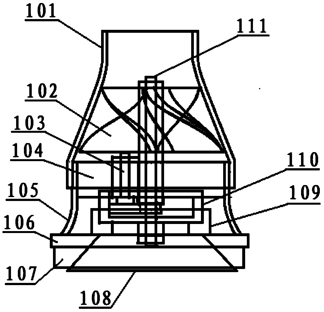
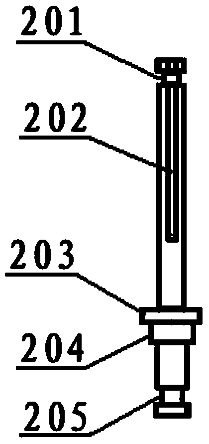
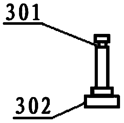
[0036] Such as Figure 1 to Figure 9 Shown is a pneumatic brush head provided by this embodiment, including a negative pressure chamber and a cleaning chamber; a turbine 102 is arranged in the negative pressure chamber; the turbine 102 is rotatably connected to the power unit; Connect the air outlet of the dust collection device; there is a brush roller in the cleaning chamber; the brush roller is rotatably connected with the power unit; the cleaning chamber is provided with an air suction port for absorbing ground dust and an air exhaust port for communicating with the air inlet; The air duct formed by the exhaust port passes through the brush roller.

[0037] Compared with the wind-driven brush head in the prior art, the wind-driven brush head provided by the embodiment of the present invention has the turbine and the brush roller of the wind-driven brush head powered by the same set of power devices, so the turbine and the brush roller can work together . If the power pro...

Embodiment 2

[0052] Such as Figure 10 to Figure 17 Shown is another pneumatic brush head provided in this embodiment, including a negative pressure chamber 1006 and a cleaning chamber 1003; a turbine 1007 is arranged in the negative pressure chamber 1006; the turbine 1007 is rotatably connected with the power device; The air inlet and the air outlet 1008 for connecting the dust suction device; the cleaning chamber 1003 is provided with a brush roller 1002; the brush roller 1002 is rotatably connected with the power unit; the cleaning chamber 1003 is provided with an air suction port 1001 for absorbing ground dust and for The air outlet connected to the air inlet; the air channel formed by the air suction port 1001 and the air outlet passes through the brush roller 1002 .

[0053] Compared with the wind-driven brush head in the prior art, the wind-driven brush head provided by the embodiment of the present invention has the turbine and the brush roller of the wind-driven brush head powered...


PUM


Abstract

The invention relates to a pneumatic brush head which comprises a negative pressure cavity and a sweeping cavity. A turbine is arranged in the negative pressure cavity. The turbine is in rotating connection with a power device. The negative pressure cavity is provided with an air inlet and an air outlet. A brush roller is arranged in the sweeping cavity. The brush roller is in rotating connection with the power device. The sweeping cavity is provided with an air suction opening and an exhaust opening. An air channel formed by the air suction opening and the exhaust opening penetrates through the brush roller. The pneumatic brush head can be divided into a horizontal rotating pneumatic brush head and a vertical rotating pneumatic brush head, the rotating speed of the brush roller can change along with changing of air suction amount, the problem that the brush roller sweeps too much dust or garbage into the sweeping cavity is avoided, the problem that the sweeping cavity is full, so that dust or garbage is raised outside the pneumatic brush head and pollutes air is avoided, meanwhile, power provided by the power device can be lowered, and energy is saved. The pneumatic brush head is compact in structure and convenient to assemble and disassemble. For a vacuum sweeping vehicle, a set of power device is saved, if three brush heads are arranged, three sets of motors are saved, production cost can be lowered, and machine body weight can be lowered.

Description

technical field [0001] The invention relates to the field of dust removal equipment, in particular to a pneumatic brush head. Background technique [0002] At present, the lower part of the sanitation sweeper is equipped with two horizontal swirl wind brush heads and one vertical swirl wind brush head. walking path. [0003] Regardless of whether it is a flat-rotating pneumatic brush head or a vertical-rotating pneumatic brush head, these pneumatic brush heads include turbines and brush rollers. The turbine and the brush roller are respectively powered by two sets of power devices, that is, one set of power device provides the rotating power for the brush roller, so that the brush roller cleans the road dust and garbage into the wind-driven brush head, and the other set of power device provides the power for the turbine. The rotating power and the rotation of the turbine generate negative pressure, so that the raised dust and garbage are sucked into the garbage storage dev...

Claims


Application Information

Patent Timeline
Patent Type & Authority Applications(China)
IPC IPC(8): E01H1/08
Inventor 左志宽
Owner 左志宽
Learn More