
Truss concrete superposed beam

A technology of concrete and composite beams, which is applied to structural elements, building components, and long-strip structural components for load-bearing, etc., can solve problems such as difficult control of construction quality, restricted floor construction speed, and limited shelving length, etc., to achieve The effect of reducing labor and material costs, simple and fast on-site construction, and improving construction speed

Active Publication Date: 2014-04-09
SHANGHAI IRON & STEEL TECHN INST
View PDF7 Cites 6 Cited by
  • Summary
  • Abstract
  • Description
  • Claims
  • Application Information

AI Technical Summary

Problems solved by technology

Among the commonly used concrete beams at present: during the construction of cast-in-place beams, temporary supports, supporting formwork, and large amount of on-site reinforcement work are required, which brings problems such as slow construction speed, high labor demand, and difficult control of construction quality; ordinary concrete composite beams , although there is no need for formwork support, temporary support, reinforcement and binding are still required, and because of the existence of stirrups, the shelf length of the assembled (integral) floor slab is very limited, which almost directly determines that the floor must be provided with temporary support. Then the construction speed of the whole floor is severely restricted, and the demand for labor and the cost will also increase to a certain extent.

Method used


Image

  • Truss concrete superposed beam
  • Truss concrete superposed beam
  • Truss concrete superposed beam

Examples


Embodiment Construction

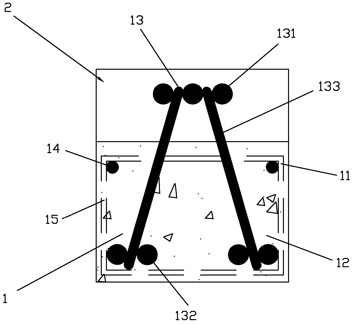
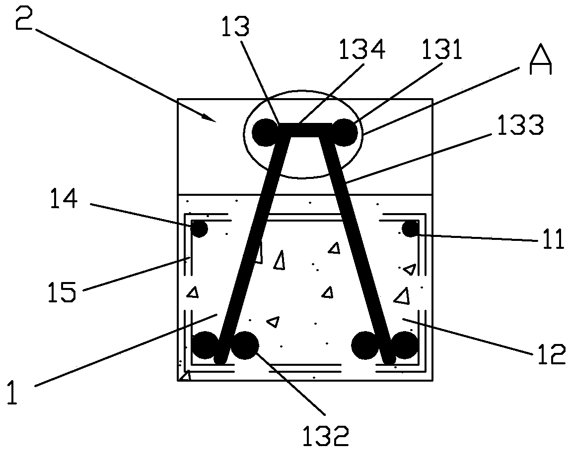
[0044] See figure 1 , figure 2 The truss concrete composite beam of the present invention includes a prefabricated layer 1, which includes a truss steel mesh 11 and a lower concrete layer 12; the truss steel mesh 11 includes a truss 13, erecting steel bars 14 and a number of hoops thereon The rib 15; the truss 13 includes an upper chord 131, a lower chord 132 and a web member 133 connecting the two; the upper chord 131 of the truss is located above the precast concrete 12; the laminated layer 2, which is located in the precast For the cast-in-situ concrete layer on layer 1, in the laminated layer 2, no additional steel bars are provided except for the beams themselves at the support.

[0045] The truss 13 of the present invention is a triangular truss, including three upper chords 131 arranged in parallel and spaced apart, four lower chords 132 arranged in parallel, and two webs 133; the upper and lower chords 131 and 132 are connected by the webs 133; The upper part of the two...


PUM


Abstract

The invention discloses a truss concrete superposed beam comprising a prefabricated layer and a superposed layer, wherein the prefabricated layer comprises a truss reinforcing mesh and a concrete layer at the lower part of the truss reinforcing mesh; the truss reinforcing mesh comprises a truss, erection steel bars and stirrups; the truss comprises a lower chord member, an upper chord member and a web member for connecting the lower chord member and the upper chord member; the upper chord member of the truss is positioned above the concrete of the prefabricated layer; the superposed layer is a cast-in-place concrete layer positioned on the prefabricated layer. The truss concrete superposed beam disclosed by the invention has the advantages of convenience and quickness in construction without temporary shoring, capability of providing a relatively longer laying length for a floor slab, quality guarantee, good integrity and good economical efficiency.

Description

Technical field [0001] The invention relates to the technical field of building components, in particular to a truss concrete composite beam. Background technique [0002] The construction of the floor is the main control item in the construction of the building structure, which has an important direct impact on the construction period, quality, cost and labor demand of the project. In the most widely used beamed floor, the beam is the support of the slab, and the construction of the slab is directly affected by the beam. Among the commonly used concrete beams at present: the construction of cast-in-place beams requires temporary supports, supporting templates, and large quantities of on-site steel bars, which causes problems such as slow construction speed, high labor demand and difficult control of construction quality; ordinary concrete laminated beams Although there is no need to support formwork, temporary supports, penetrating ribs and lashing are still required. Due to th...

Claims


Application Information

Patent Timeline
Patent Type & Authority Applications(China)
IPC IPC(8): E04C3/293
Inventor 张昭祥蒋路贾正桐孙绪东
Owner SHANGHAI IRON & STEEL TECHN INST
Learn More