Wireless non-contact scene switch
A non-contact, wireless technology, used in the control of contactors, relays, and motors, can solve the problems of inflexible operation and use, limited service life, easy to be contaminated with dust, etc., and achieve rich control functions, stable control, and implementation methods. simple effect
- Summary
- Abstract
- Description
- Claims
- Application Information
AI Technical Summary
Problems solved by technology
Method used
Image

Examples
Embodiment 1
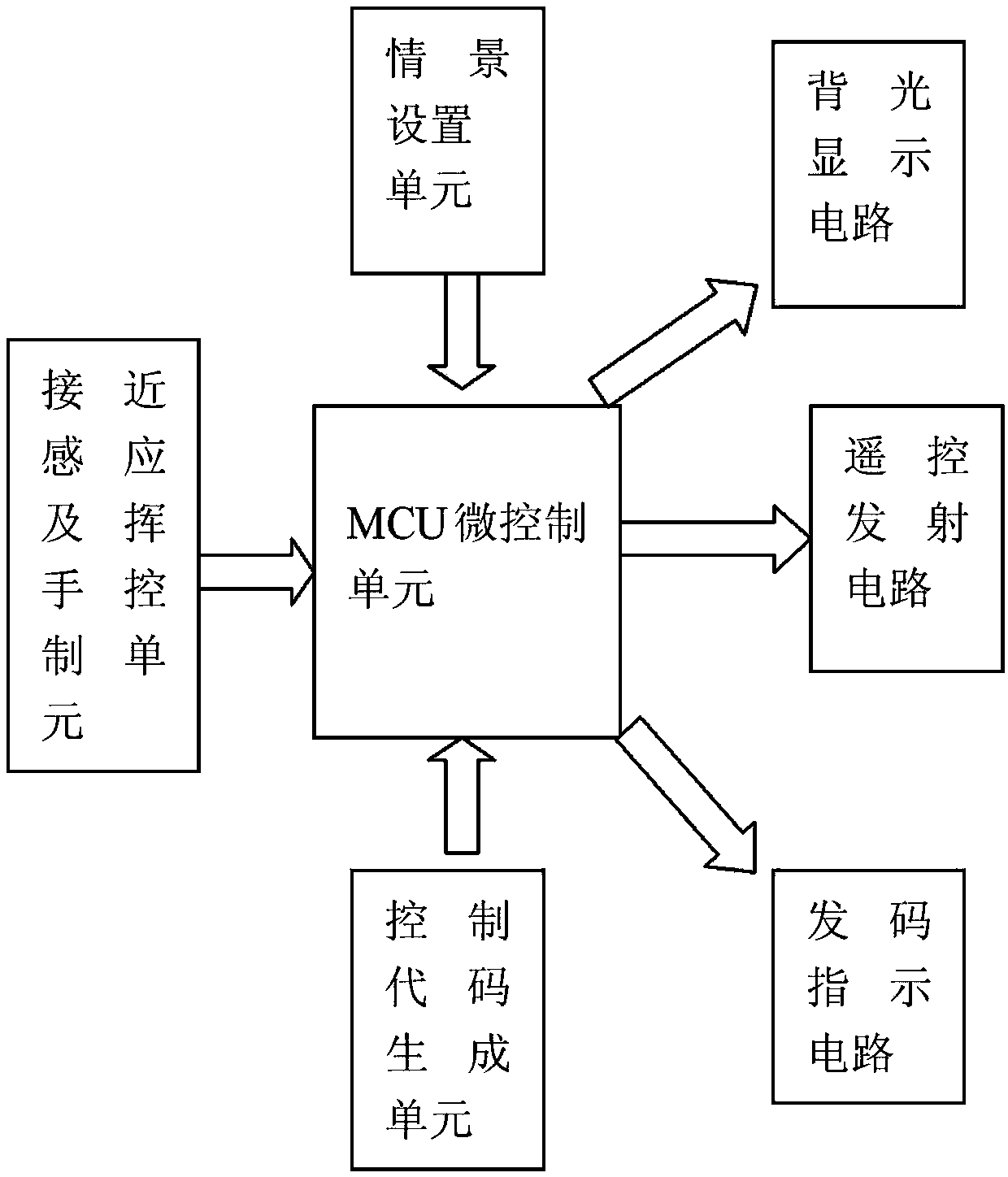
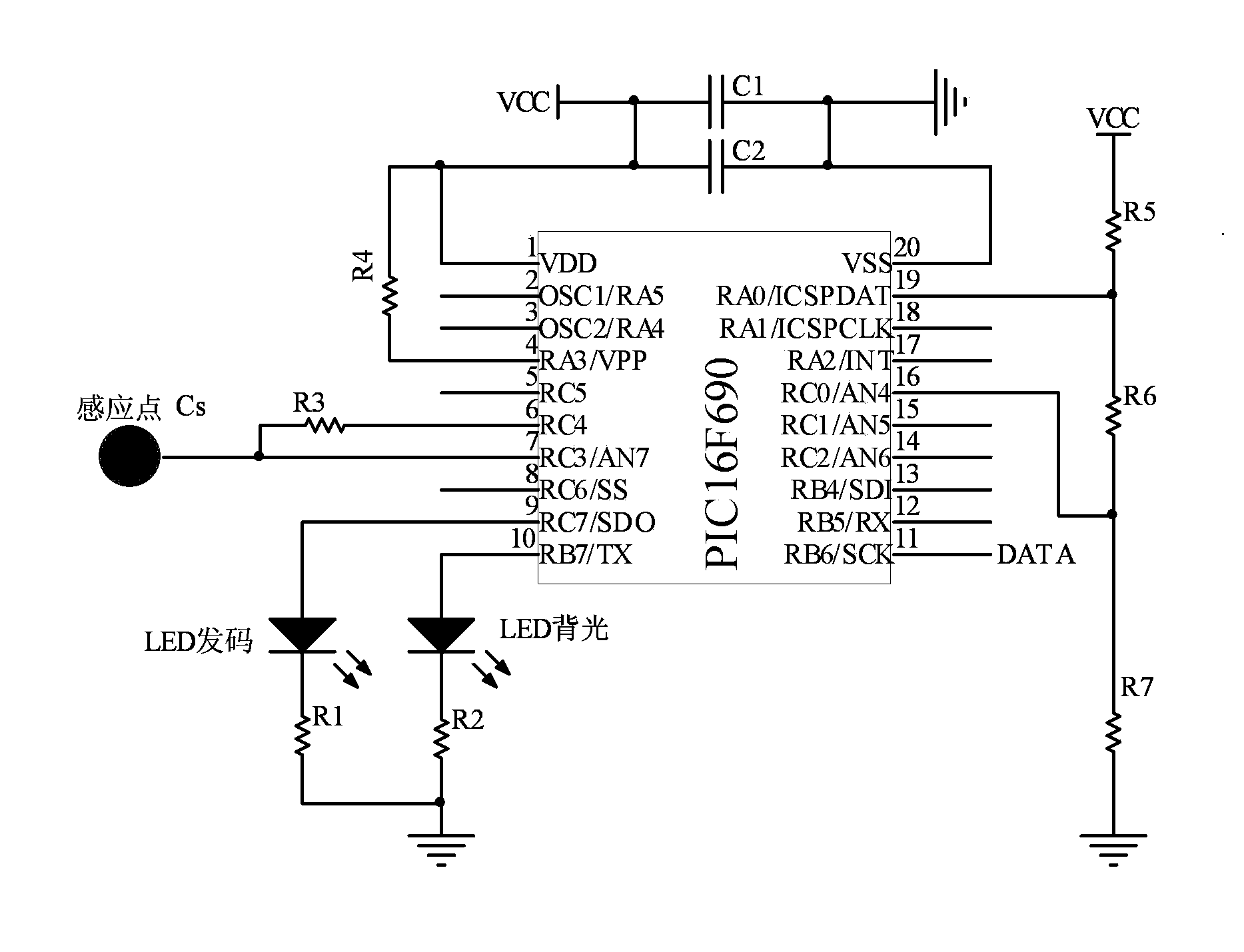
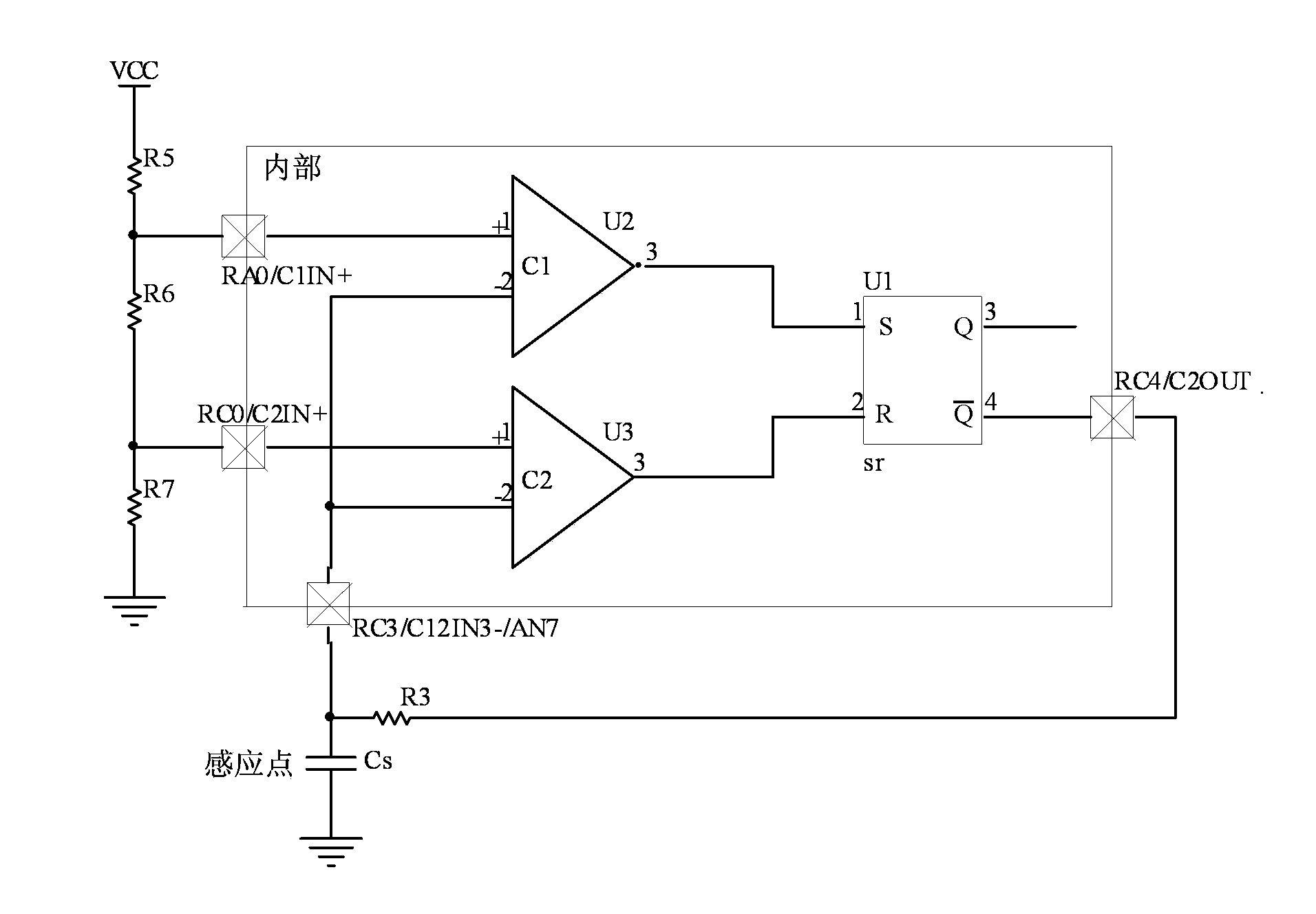
[0032] see figure 1 , figure 2 In this embodiment, the wireless non-contact scene switch includes a power supply unit, an MCU micro-control unit, and a remote control transmitting circuit. The MCU micro-control unit is implemented by any single-chip microcomputer of the PIC16F616 series, PIC16F690 series or PIC16F887 series. The scene switch Contains proximity sensing and hand waving control unit, the proximity sensing and hand waving control unit uses the RC oscillator of the MCU itself to realize the sensing of proximity and gesture signals, and three clamping resistors R5 and R6 are connected in series between the positive and negative poles of the power supply , R7, wherein the nodes of resistors R5 and R6 are connected to the RA0 pin of the MCU, the nodes of the resistors R6 and R7 are connected to the RC0 pin of the MCU, the RC3 pin of the MCU is connected to the natural parasitic capacitance Cs to the ground, and the RC3 pin of the MCU is connected to the RC4 pin Ther...
Embodiment 2
[0036] see figure 1 , figure 2 , image 3 . The wireless non-contact scene switch of this embodiment is different from Embodiment 1 or Embodiment 2 in that it is connected with the output end of the MCU micro control unit with a backlight display circuit, and the backlight display circuit is composed of an LED and a current limiting resistor. Composed of R1, lead out from the RB7 / TX pin of the MCU.
[0037]The function of the backlight display circuit is: when a person approaches the switch, the backlight is turned on.
[0038] At the same time, a code sending indicating circuit is connected with the output end of the MCU micro control unit, and the code sending indicating circuit is composed of an LED and a current limiting resistor R2, and is drawn from the RC7 / SDO pin of the MCU.
[0039] The function of the code sending indicating circuit is: when the waving control operation takes effect, the LED flashes to indicate that the operation is successful.
Embodiment 3
[0041] see figure 1 , figure 2 , image 3 , Figure 4 . The wireless non-contact scene switch of this embodiment is different from the foregoing embodiments in that it specifically discloses a remote control transmitting circuit. see Figure 4 , The remote control transmitter circuit is built with PT4455 or PT4450 integrated circuit chip or discrete components. The input terminal DATA of the remote control transmitting circuit is connected with the output terminal BR6 / SCK of the MCU micro control unit. The wireless transmission frequency can be 433M or 315M, and the transmission frequency of the transmission circuit can also be realized by 868M or 2.4G frequency. The output of the transmitting circuit adopts the board-mounted PCB antenna, which has a simple structure and good effect.
[0042] The function of the remote control transmitter circuit is to execute the instructions of the MCU micro-control unit, and transmit the coded signal corresponding to the scene setti...
PUM
 Abstract
Description
Claims
Application Information
 - Generate Ideas
- Intellectual Property
- Life Sciences
- Materials
- Tech Scout
- Unparalleled Data Quality
- Higher Quality Content
- 60% Fewer Hallucinations
Browse by: Latest US Patents, China's latest patents, Technical Efficacy Thesaurus, Application Domain, Technology Topic, Popular Technical Reports.
© 2025 PatSnap. All rights reserved.Legal|Privacy policy|Modern Slavery Act Transparency Statement|Sitemap|About US| Contact US: help@patsnap.com