Control method of three-phase photovoltaic grid-connected inverter when grid voltage is unbalanced
A grid voltage and inverter technology, applied in the field of three-phase photovoltaic grid-connected inverter control, can solve the problems of grid-connected converter heating, unclear reference current setting method, power oscillation, etc.
- Summary
- Abstract
- Description
- Claims
- Application Information
AI Technical Summary
Problems solved by technology
Method used
Image

Examples
Embodiment 1
[0062] Depend on Figure 1-6 It can be seen from the described embodiment that this embodiment includes the following steps:
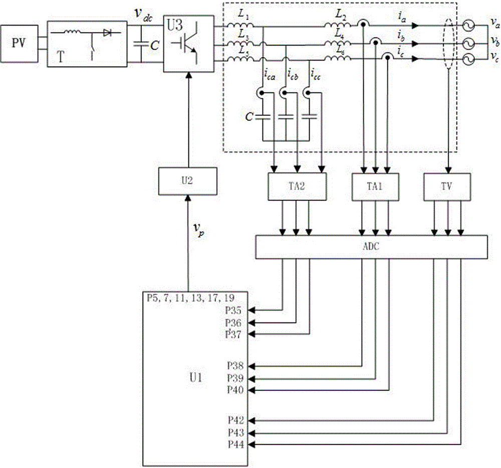
[0063] Step 1 Establish the main circuit and inverter control system of the three-phase photovoltaic grid-connected system, which includes solar photovoltaic cell array PV, boost circuit T, filter capacitor C, grid-connected inverter U3, LCL filter, the first current Transformer TA1, second current transformer TA2, voltage transformer TV, DSP controller U1, drive circuit U2 and analog-to-digital converter ADC; the output terminal of the solar photovoltaic cell array PV passes through the step-up circuit T, The filter capacitor C is connected to the input terminal of the grid-connected inverter U3; the output terminal of the grid-connected inverter U3 is connected to the grid through the LCL filter; the first current transformer TA1 and the voltage transformer TV are respectively Installed on the output line of the grid side end of the LCL filter; the ...
Embodiment 2
[0099] Step 6 in the second embodiment is different from step 6 in the first embodiment, and the others are the same as the first embodiment.
[0100] Step 6 of present embodiment two is as follows:
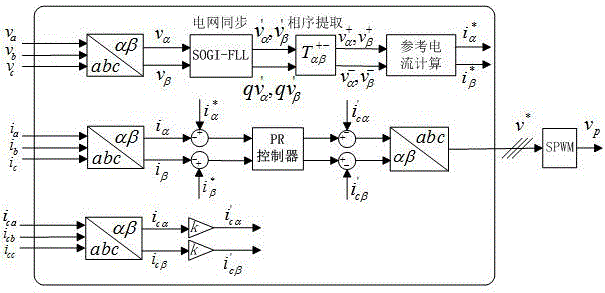
[0101] Step 6 The steps of reference current calculation;
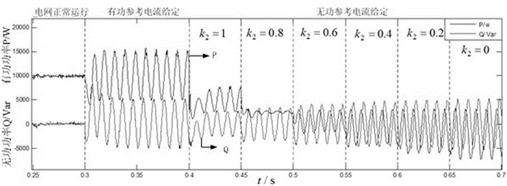
[0102] When an asymmetrical fault occurs in the power grid, at 0.3s~0.4s (see Figure 5-6 ) still inject active reference current into the power grid, at this time the component of the active reference current in the stationary coordinate system , for:
[0103] ;
[0104] in, P* It is the active power converted by the photovoltaic array, and its value is 10000W.
[0105] Effect description: At this time, the inverter can still work stably, but the grid-side voltage drops and the current increases. Excessive current may cause the grid protection device to operate. And the active power and reactive power start to oscillate.
Embodiment 3
[0107] Step 6 in the third embodiment is different from step 6 in the first embodiment, and the others are the same as the first embodiment.
[0108] Step 6 of present embodiment three is as follows:
[0109] Step 6 The steps of reference current calculation;
[0110] When an asymmetrical fault occurs in the grid, during 0.4s-0.45s (see Figure 5-6 ), using the reactive reference current control method, k 2 =1, the component of the reference current in the stationary coordinate system , for:
[0111] ,
[0112] current limit value I= 30A, k 2 =1, Q* The expression is:
[0113] ,
[0114] Effect description: The voltage of each phase on the grid side has been improved, and the current on the grid side is limited within 30A. Active power oscillation still exists, but it is weaker than before using the strategy.
PUM
 Abstract
Description
Claims
Application Information