Stator core, split core block, stator manufacturing method and rotary electric machine

A stator core and split core technology, which is applied in the manufacture of stator/rotor bodies, motor generators, electrical components, etc., can solve the problems of increasing stator core iron loss and achieve the effect of reducing iron loss

Inactive Publication Date: 2014-04-09
YASKAWA DENKI KK
View PDF5 Cites 18 Cited by
  • Summary
  • Abstract
  • Description
  • Claims
  • Application Information

AI Technical Summary

Problems solved by technology

[0005] However, in the configuration disclosed in Japanese Patent Laid-Open No. 2006-311738, since the connection portion is formed by caulking, the iron loss in the stator core increases

Method used


Image

  • Stator core, split core block, stator manufacturing method and rotary electric machine
  • Stator core, split core block, stator manufacturing method and rotary electric machine
  • Stator core, split core block, stator manufacturing method and rotary electric machine

Examples


Embodiment Construction

[0023] The embodiments of the stator core, the discrete core group, the method of manufacturing the stator, and the rotating electric machine disclosed herein will now be described in detail with reference to the drawings constituting a part of the present invention. However, the present invention is not limited to the following embodiments.

[0024] (Stator core)

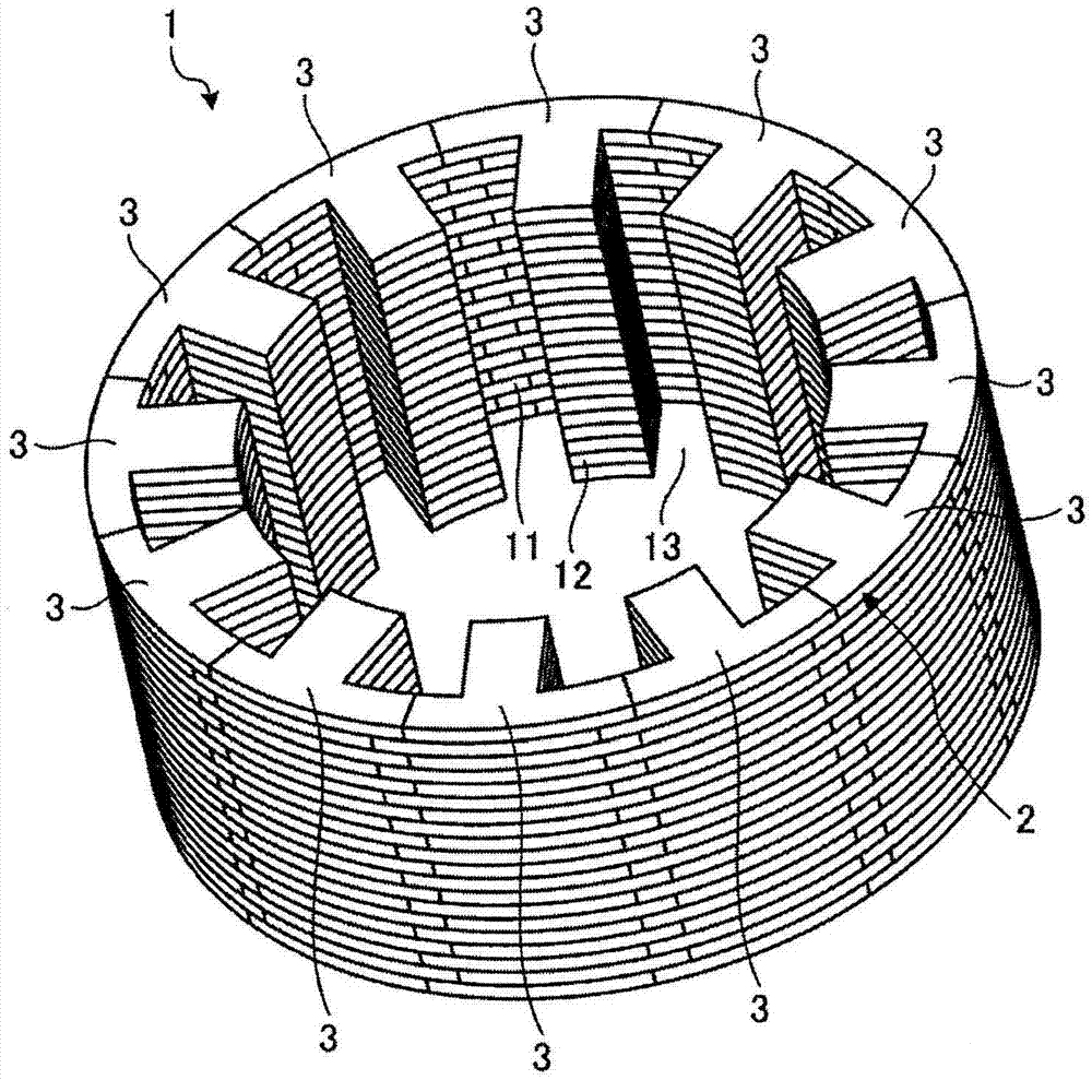
[0025] First, the stator core according to the preferred embodiment will be briefly described with reference to the drawings. figure 1 It is a perspective view showing the stator core 1 according to the preferred embodiment.

[0026] The stator core 1 according to the preferred embodiment is used in, for example, a motor 10 to be described later (see Picture 11 ). Such as figure 1 As shown in the figure, the stator core 1 is formed by laminating a plurality of metal annular core plates 2 up and down. The number of the core plates 2 laminated in this way can be appropriately set according to desired characteristics. Su...


PUM


Abstract

The invention provides a stator core, a split core block, a stator manufacturing method and a rotary electric machine. The stator core is formed by laminating a plurality of annular core plates one on top of another. The stator core includes a cylindrical yoke and a plurality of radially protruding teeth arranged at a specified interval along a circumferential direction of the yoke. Each of the core plates includes a plurality of annularly-arranged split cores each having a yoke portion forming the yoke and a tooth portion protruding from the yoke portion and forming the teeth. The yoke portion includes a first yoke section and a second yoke section extending different lengths at opposite lateral sides of the tooth portion.

Description

Technical field [0001] The embodiments disclosed herein relate to a stator core, a discrete core group, a method of manufacturing a stator, and a rotating electric machine. Background technique [0002] Conventionally, a stator core formed of a plurality of annular core plates laminated one above the other is available. The stator core includes a cylindrical yoke and a plurality of teeth arranged at predetermined intervals in the circumferential direction of the yoke. These teeth protrude inward from the yoke. [0003] For the stator core of such a laminated structure, a stator core is known in which a plurality of divided cores each having teeth are interconnected by a joint formed by caulking or the like to form a core plate (see, for example, Japanese Patent Laid-Open 2006 -Bulletin No. 311738). [0004] Using these core plates makes it possible to perform winding in a state where the core plates are linearly opened by the joint. This helps to improve the efficiency of the win...

Claims


Application Information

Patent Timeline
Patent Type & Authority Applications(China)
IPC IPC(8): H02K1/12H02K1/14H02K15/02
CPCH02K15/024H02K1/16H02K1/148Y10T29/49009
Inventor 入江一明
Owner YASKAWA DENKI KK
Why Eureka
Try Eureka