
Permanent magnet synchronous motor sliding-mode speed observer driven by two-stage matrix converter

A technology of matrix converter and speed observer, which is applied in the direction of electronically commutated motor control, motor generator control, control generator, etc., can solve the problems of heavy table construction, time delay, jitter of sliding mode observer, etc. Achieve the effect of eliminating large workload and small input current harmonics

Inactive Publication Date: 2014-04-09
XIAN UNIV OF TECH
View PDF5 Cites 29 Cited by
  • Summary
  • Abstract
  • Description
  • Claims
  • Application Information

AI Technical Summary

Problems solved by technology

[0009] The purpose of the present invention is to provide a permanent magnet synchronous motor sliding mode speed observer driven by a double-stage matrix converter, which solves the problems of the sliding mode observer in the prior art, such as jitter, time delay, heavy table building workload and waste of storage space And other issues

Method used


Image

  • Permanent magnet synchronous motor sliding-mode speed observer driven by two-stage matrix converter
  • Permanent magnet synchronous motor sliding-mode speed observer driven by two-stage matrix converter
  • Permanent magnet synchronous motor sliding-mode speed observer driven by two-stage matrix converter

Examples


Embodiment Construction

[0036] The present invention will be described in detail below in conjunction with the accompanying drawings and specific embodiments.

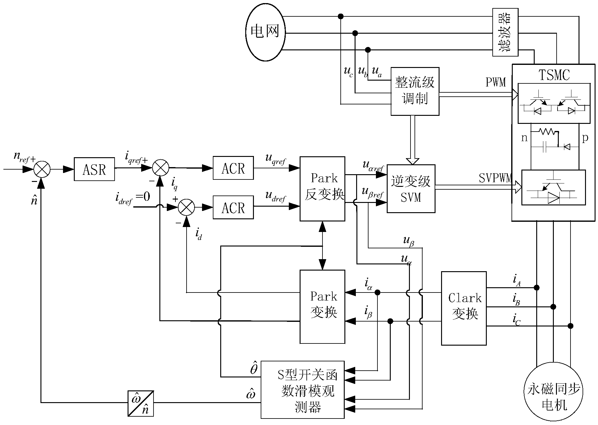
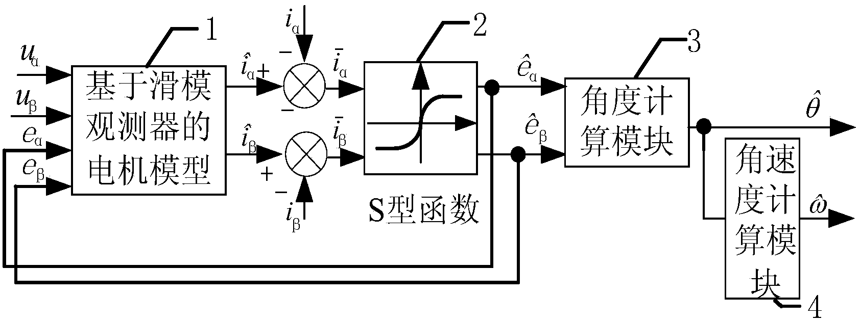
[0037] Sliding mode velocity observer of permanent magnet synchronous motor driven by double-stage matrix converter, including motor model 1 based on sliding mode observer, S-type switching function 2, angle calculation module 3 and angular velocity calculation module 4; permanent magnet synchronous motor two-phase The stator voltage u in the stationary coordinate system α and u β Obtain 2 outputs with S-type switching function through voltage reconstruction and As the input of the motor model 1 based on the sliding mode observer, the motor model 1 based on the sliding mode observer outputs the stator current observation value Subtract the stator actual current value i α i β , the difference As the input of the S-type switching function 2, the estimated value of the back EMF in the two-phase stationary coordinate system is output ...


PUM


Abstract

A permanent magnet synchronous motor sliding-mode speed observer driven by a two-stage matrix converter comprises a motor model based on the sliding-mode observer, an S-shaped switch function, an angle calculation module and an angular speed calculation module. Ualpha and Ubeta, obtained through the voltage reconstitution method, of stator voltages in a two-phase static coordinate system of a permanent magnet synchronous motor and the two S-shaped switch function output values (see the specification) serve as the motor model input based on the sliding-mode observer, the stator actual current values including ialpha and ibeta are subtracted from the four motor model output stator current observing values (see the specification) based on the sliding-mode speed observer, the two difference values serve as the S-shaped switch function input, the difference values are processed through the permanent magnet synchronous motor sliding-mode speed observer, then the two counter EMF estimated values in the two-phase static coordinate system are output, the rotor position is obtained through the angle calculation module, and the angular speed is obtained through the angular speed calculation module.

Description

technical field [0001] The invention belongs to the field of permanent magnet motor control, and relates to a sliding mode velocity observer of a permanent magnet synchronous motor driven by a double-stage matrix converter. Background technique [0002] With the development of the economy, power electronic devices have been widely used in industry, but while creating huge economic benefits, they also bring huge harmonics to the power grid. Therefore, it has become a development trend to develop new power electronic devices that are environmentally friendly, compact and efficient. Two-stage Matrix Converter (Two-stage Matrix Converter, TSMC) is a new type of AC / AC "green" power converter developed in recent years, which has the advantages of less input current harmonic content, high power density, controllable input power factor, Energy can flow in both directions, and there is no energy storage capacitor on the DC side. [0003] Permanent Magnet Synchronous Motor (PMSM) do...

Claims


Application Information

Patent Timeline
IPC IPC(8): H02P21/14
Inventor 宋卫章马宝剑钟彦儒汪丽娟
Owner XIAN UNIV OF TECH
Learn More