
DMD-based imaging pre-processing device and method

An imaging and pixel technology, applied in the field of DMD-based imaging preprocessing systems, to improve dynamic range, enhance adaptability, and solve the effects of ambient lighting and field of view self-defects

Inactive Publication Date: 2014-04-09
TIANJIN UNIV
View PDF4 Cites 11 Cited by
  • Summary
  • Abstract
  • Description
  • Claims
  • Application Information

AI Technical Summary

Problems solved by technology

When light from different incident angles hits targets with different roughness, reflection and transmittance, contour depth, contour curvature and color, they will behave differently in the visual device, and imaging post-processing technology cannot fundamentally change these lighting factors

Method used


Image

  • DMD-based imaging pre-processing device and method
  • DMD-based imaging pre-processing device and method
  • DMD-based imaging pre-processing device and method

Examples


Embodiment

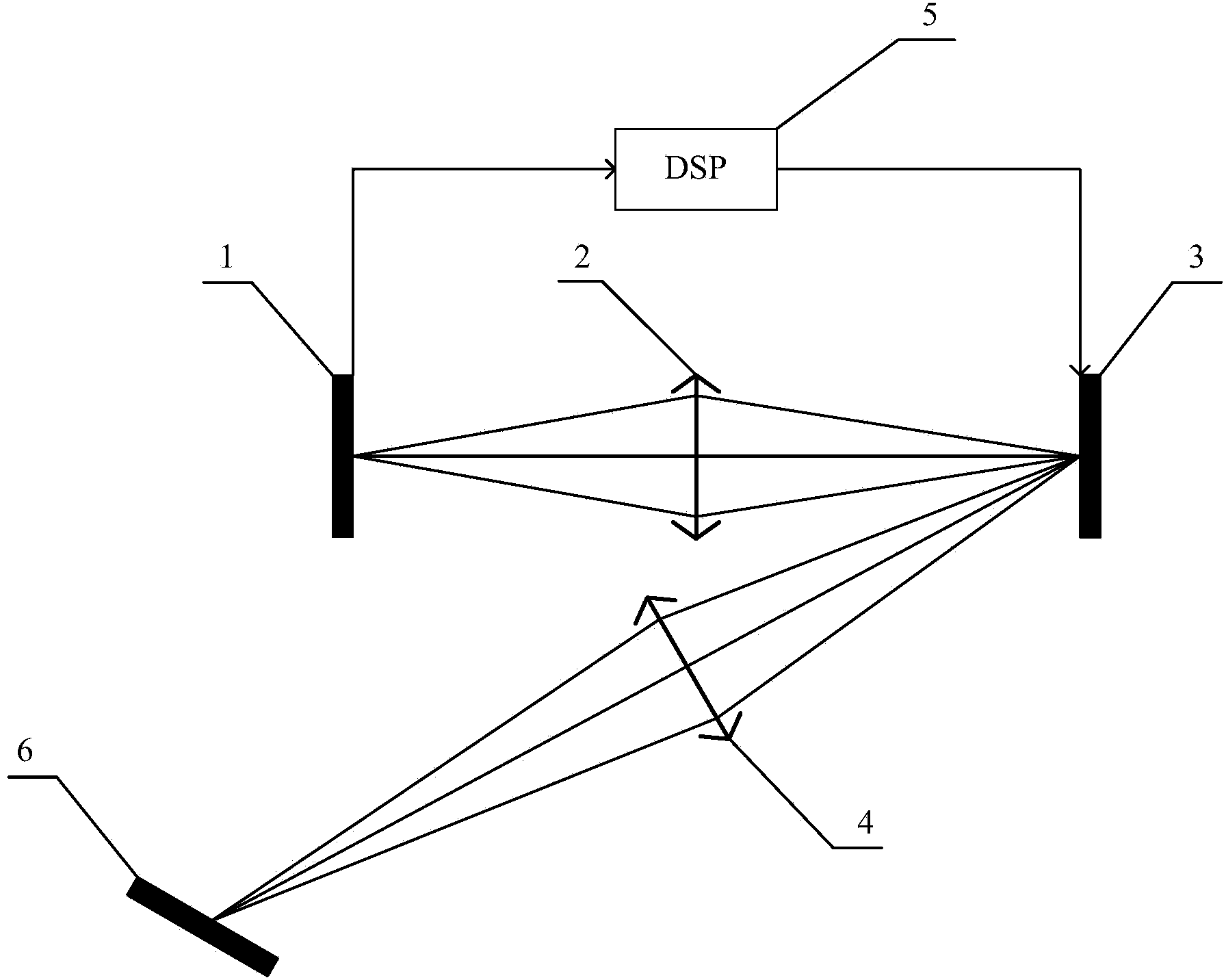
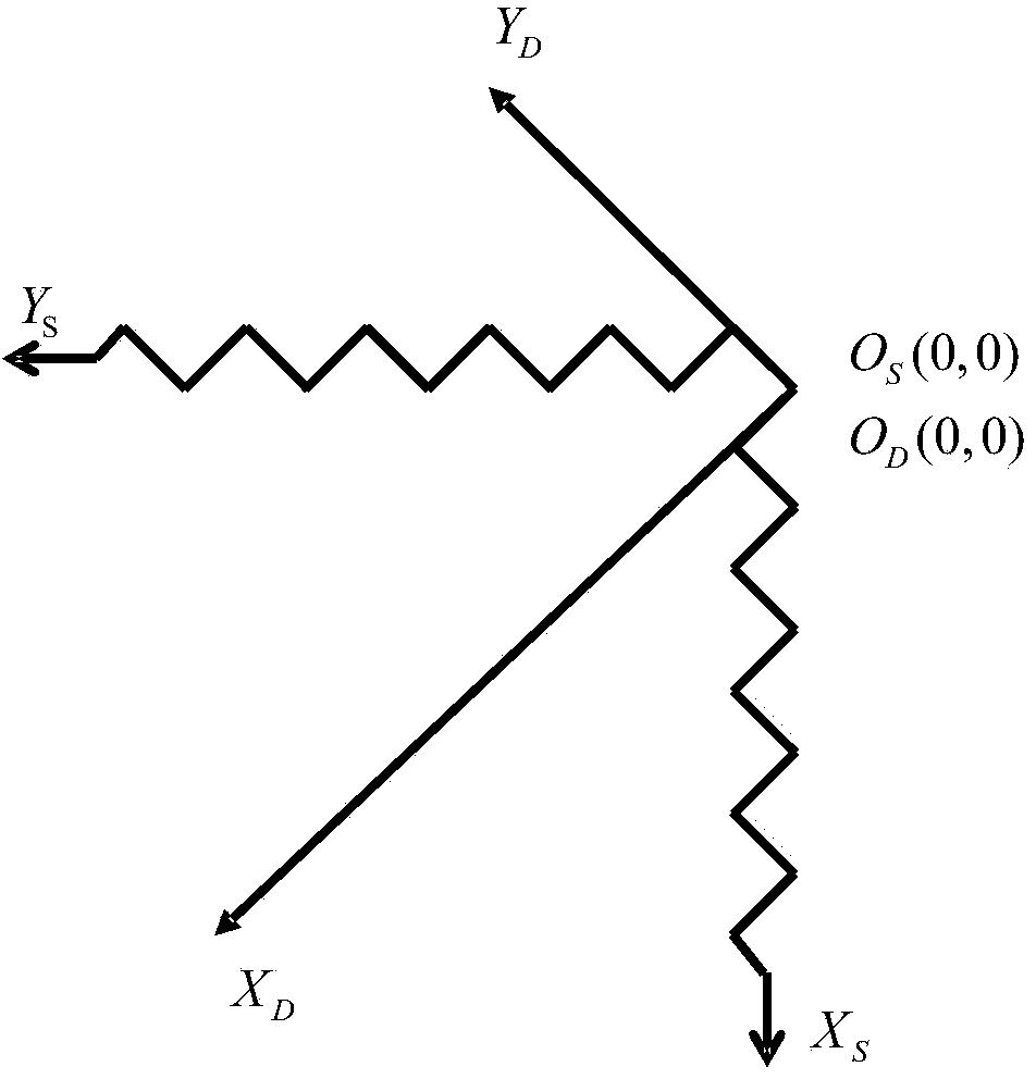
[0048] Such as figure 1 As shown, the CCD 1 with a resolution of 768×576 is selected, and the pixel size of an 8-bit single CCD 1 is 8.3×8.3 μm; the resolution of a DMD 3 is selected to be 684×608, and the pixel size of a single DMD is 7.6×7.6 μm ;Adjust the paraxial magnification of the first lens group 2 to 0.91, adjust the relative position of CCD 1 and DMD 3 vertically and horizontally to achieve precise one-to-one pixel matching, and build an imaging pre-processing system based on DMD with an effective pixel of 200,000 ; In the imaging of the corresponding relationship between CCD 1 and DMD 3, select 46 sampling points on the checkerboard to calculate the transformation matrix:

[0049] W 2 = - 0.3776 - 0.3745 99.9922 - ...


PUM


Abstract

The invention discloses a DMD-based imaging pre-processing device and a DMD-based pre-imaging processing method. The DMD-based pre-imaging processing device comprises a CCD, a first lens group, a DMD, a second lens group, a DSP and an object space working surface. Spatial one-to-one correspondence between micro mirror-image elements in the DMD and CCD pixels is realized, and coordinate corresponding relation imaging of the CCD and the DMD and corresponding relation imaging of the DMD and the object space working surface are performed, and therefore, the pre-imaging processing device can process incident light before imaging. According to the DMD-based imaging pre-processing device and method of the invention, the focus of the work of image processing is shifted from post-imaging to an optical path of pre-imaging; and corresponding imaging of the CCD and the DMD is utilized, such that the gray range index of an imaging gray histogram can be increased, and therefore, the dynamic range of an imaging system can be expanded. With the DMD-based imaging pre-processing device and method of invention adopted, defects in environmental lighting and a field of view can be eliminated, and imaging quality and visual expressivity of an object can be improved. The DMD-based imaging pre-processing device and method of the invention can be widely applied in fields such as industrial inspection, medical imaging and astronomical observation.

Description

technical field [0001] The invention relates to a computerized camera imaging system, in particular to a DMD-based imaging preprocessing system. Background technique [0002] The traditional visual imaging processing technology uses computer algorithms to analyze, process and process the captured images after imaging to meet various needs such as visual senses, feature recognition, target tracking, detection and measurement. However, the imaging post-processing technology is limited by the imaging environment and the inherent defects of the image field itself, and cannot fundamentally eliminate the imaging quality problem. For example, in the visual measurement site, the visual measurement device is affected by the surrounding light and its own structured light. When light from different incident angles strikes targets with different roughness, reflection and transmittance, contour depth, contour curvature and color, they will behave differently in the visual device, and im...

Claims


Application Information

Patent Timeline
IPC IPC(8): H04N5/232G02B17/02
Inventor 赵首博曲兴华张福民
Owner TIANJIN UNIV
Learn More