
Control channel resource allocation method and base station

A technology of control channel resource and allocation method, applied in the field of control channel resource allocation method and base station, can solve problems such as difficulty in adaptation, limited system capacity, and failure to take into account the uncertainty of communication system business data transmission characteristics, etc. The effect of increasing capacity

Inactive Publication Date: 2014-04-09
POTEVIO INFORMATION TECH CO LTD
View PDF3 Cites 25 Cited by
  • Summary
  • Abstract
  • Description
  • Claims
  • Application Information

AI Technical Summary

Problems solved by technology

[0006] The inventors of the present invention found in the process of implementing the present invention that: the existing two schemes for allocating control channel resources are to statically allocate the number of OFDM symbols occupied by the PDCCH, that is, to determine in advance the number of OFDM symbols occupied by the PDCCH channel before using the PDCCH channel to carry downlink control information The number of OFDM symbols occupied by the required PDCCH cannot be adjusted later, so as to realize the time-domain resource control of the PDCCH. Since the number of OFDM symbols occupied by the PDCCH is mainly statically allocated in the prior art, the two allocation schemes It does not take into account the number of communication system services and the uncertainty of service data transmission characteristics. This static method of allocating control channel resources is difficult to adapt to the real situation of system load and service data transmission characteristics, resulting in limited system capacity.

Method used


Image

  • Control channel resource allocation method and base station
  • Control channel resource allocation method and base station
  • Control channel resource allocation method and base station

Examples


Embodiment Construction

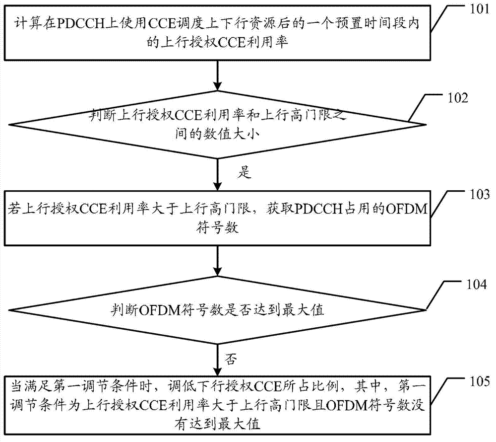
[0030] Embodiments of the present invention provide a method for allocating control channel resources and a base station, which are used to realize the control and allocation of time domain resources of PDCCH and improve the capacity of the communication system.

[0031] In order to make the purpose, features and advantages of the present invention more obvious and understandable, the technical solutions in the embodiments of the present invention will be clearly and completely described below in conjunction with the accompanying drawings in the embodiments of the present invention. Obviously, the following The described embodiments are only some, not all, embodiments of the present invention. All other embodiments obtained by those skilled in the art based on the embodiments of the present invention belong to the protection scope of the present invention.

[0032] The method for allocating control channel resources provided by the embodiment of the present invention, such as ...


PUM


Abstract

The embodiments of the invention disclose a control channel resource allocation method and a base station, for realizing control allocation of time domain resources of a PDCCH and improving the capacity of a communication system. The method comprises the following steps: calculating the utilization rate of an uplink authorization CCE within a preset time period after uplink and downlink resources are scheduled by use of a CCE on the PDCCH; determining which one is greater in term of value from the utilization rate of the uplink authorization CCE and an uplink high threshold; if the utilization rate of the uplink authorization CCE is greater than the uplink high threshold, obtaining the sign digits of OFDM (orthogonal frequency division multiplexing) occupied by the PDCCH; determining whether the sign digits of the OFDM reach the maximum value; and when a first adjusting condition is met, lowering the proportion occupied by a downlink authorization CCE, wherein the proportion occupied by the downlink authorization CCE refers to a ratio of the number of CCEs for downlink scheduling to the total number of CEEs mapped to the PDCCH, and the first adjusting condition is that the utilization rate of the uplink authorization CCE is greater than the uplink high threshold and the sign digits of the OFDM do not reach the maximum value.

Description

technical field [0001] The present invention relates to the technical field of wireless communication, in particular to a method for allocating control channel resources and a base station. Background technique [0002] In the Long Term Evolution (LTE, Long Term Evolution) system, the downlink control region is used to carry downlink control signaling, usually occupying the first 1 to 3 Orthogonal Frequency Division Multiplexing (OFDM, Orthogonal Frequency Division Multiplexing) of a downlink subframe symbols, and other symbols are assigned to downlink traffic channels to transmit downlink traffic data. The downlink control area includes Physical Control Format Indicator Channel (PCFICH, Physical Control Format Indicator Channel), Physical Hybrid Automatic Repeat Request Indicator Channel (PHICH, Physical Hybrid-ARQ Indicator Channel) and Physical Downlink Control Channel (PDCCH, Physical Downlink Control Channel) . The PCFICH in each downlink subframe carries control form...

Claims


Application Information

Patent Timeline
Patent Type & Authority Applications(China)
IPC IPC(8): H04W72/04H04W88/08H04L27/26
Inventor 于瑞芷韦玮吕征南
Owner POTEVIO INFORMATION TECH CO LTD
Learn More