Optical element of a laser material machining tool, laser machining head having an optical element, and method for operating a laser machining tool

A laser processing head and optical element technology, applied in the direction of optical elements, optics, manufacturing tools, etc., can solve the problems of optical element pollution, aging, wear and so on

Active Publication Date: 2014-04-09
TRUMPF WERKZEUGMASCHINEN GMBH & CO KG
View PDF5 Cites 5 Cited by
  • Summary
  • Abstract
  • Description
  • Claims
  • Application Information

AI Technical Summary

Problems solved by technology

However, some special problems occur in laser material processing in the high power field
In particular, optical components may be contaminated and / or worn or aged

Method used


Image

  • Optical element of a laser material machining tool, laser machining head having an optical element, and method for operating a laser machining tool
  • Optical element of a laser material machining tool, laser machining head having an optical element, and method for operating a laser machining tool
  • Optical element of a laser material machining tool, laser machining head having an optical element, and method for operating a laser machining tool

Examples


Embodiment Construction

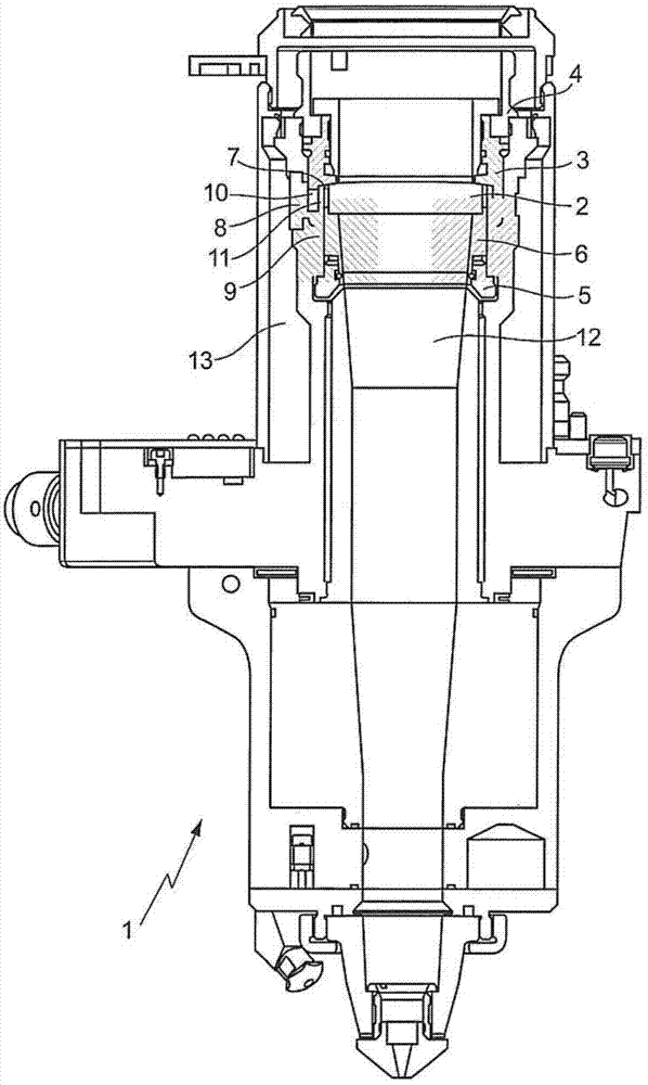
[0040] figure 1 A longitudinal sectional view of a laser processing head 1 designed as a laser cutting head of a laser material processing machine is shown. The laser processing head 1 has an optical element 2 configured as a lens. The optical element is arranged in a lens barrel 3 , wherein the lens barrel 3 is replaceable, in particular removable from the laser processing head 1 . A threaded ring 4 is shown at the upper end of the lens barrel 3 , which holds the lens barrel in the laser processing head 1 . The threaded ring 5 holds the optical element 2 in the lens barrel 3 and thus in the laser processing head 1 through a spacer 6 .

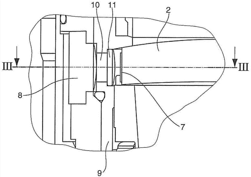
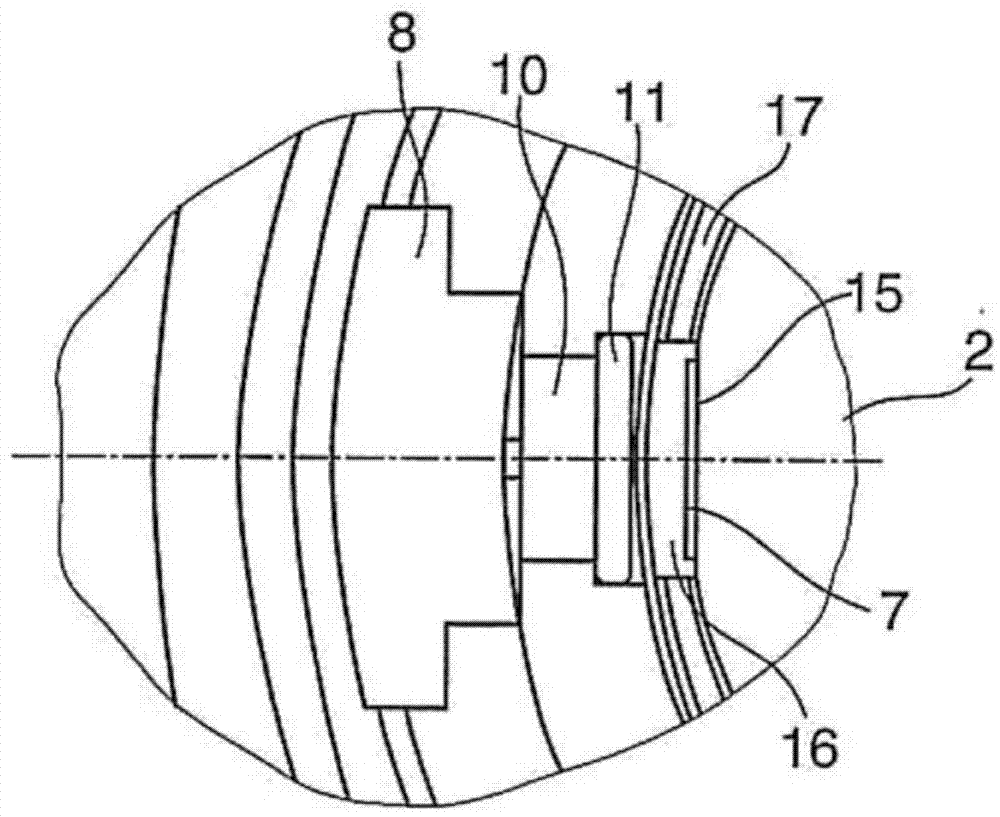
[0041] Arranged on the optical element 2 is a transponder 7 in the form of a radio frequency identification tag (RFID tag). The transponder is opposite the reading and / or writing device 8 . Information from the transponder 7 can be read out by means of the reading and / or writing device 8 and information can also be written into the transpo...


PUM


Abstract

The invention relates to an optical element (2) intended for installing in a laser material machining tool and having first surface that is optically unused and/or not captured by the laser beam during operation of the laser machining tool, wherein a transponder (7) is arranged in the region of the surface and comprises readable information with respect to the optical element (2).

Description

technical field [0001] The invention relates to an optical element defined for installation in a laser material processing machine. [0002] Furthermore, the invention relates to a laser processing head with an optical element and a method for operating a laser material processing machine. Background technique [0003] The laser material processing machine has a laser processing head which may comprise at least one lens as an optical element etc. or, in the case of a YAG laser material processing machine, as an optical element in addition to the lens as an optical element and a protective window. In the field of laser material processing, optical components do not have identification marks beyond the laser-engraved material number and production date. However, some particular problems occur in laser material processing in the high power field. In particular, optical components may be contaminated and / or worn or aged. Getting information about these and using that informa...

Claims


Application Information

Patent Timeline
Patent Type & Authority Applications(China)
IPC IPC(8): B23K26/70G02B27/00
CPCB23K26/422B23K26/428B23K26/03B23K26/702B23K26/707B23K26/064B23K26/70
Inventor J-M·韦克T·鲁普D·韦埃斯
Owner TRUMPF WERKZEUGMASCHINEN GMBH & CO KG
Why Eureka
Try Eureka