Punching machine with mould capable of being displaced

A punching machine and die technology, applied in the direction of forming tools, manufacturing tools, metal processing equipment, etc., can solve the problems such as the inability of the concave die to be transposed, the operator's technical requirements are not high, and there are no conveyor belt moldings, etc., to achieve simple structure, Improve production efficiency and design reasonable effect

Inactive Publication Date: 2014-04-16
KUNSHAN HUAKUI MACHINERY ELECTRONICS
View PDF5 Cites 8 Cited by
  • Summary
  • Abstract
  • Description
  • Claims
  • Application Information

AI Technical Summary

Problems solved by technology

In national production, the stamping process has the advantages of saving materials and energy, high efficiency, low technical requirements for operators, and the ability to produce products that cannot be achieved by mechanical processing through various mold applications. Its use is becoming more and more extensive. At present, the die of the stamping machine cannot be transposed. When there are multiple stamping heads on the stamping device, if the mold cannot be transposed, the stamping machine cannot immediately press the plate once. Realizing the rotation of the plate on the mold will affect the production efficiency of the punching machine. At the same time, there is no conveyor belt to realize the next step of the formed parts quickly. In order to solve the above problems, a new technical solution is provided.

Method used


Image

  • Punching machine with mould capable of being displaced

Examples


Embodiment Construction

[0010] In order to make the object, technical solution and advantages of the present invention clearer, the present invention will be further described in detail below in conjunction with the accompanying drawings and embodiments. It should be understood that the specific embodiments described here are only used to explain the present invention, not to limit the present invention.

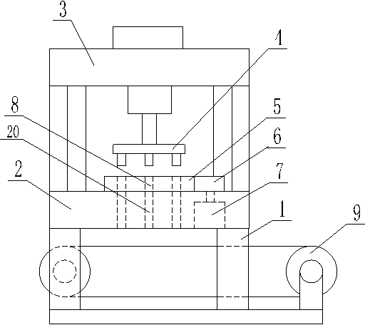
[0011] see figure 1 , figure 1 It is a structural schematic diagram of the present invention.

[0012] A stamping machine with a variable mold position, comprising a support leg 1, the upper end of the support leg 1 is provided with a lower mold base 2, the lower mold base 2 is connected with an upper mold base 3 through a support column, and the upper mold base 3 is provided with a stamping device 4, and the stamping device 4 is provided with a plurality of stamping heads. The lower mold base 2 is provided with a mold 5, and the mold 5 is engaged with the driving wheel 6, and the driving wheel ...


PUM


Abstract

The invention relates to a punching machine with a mould capable of being displaced. The punching machine with the mould capable of being displaced comprises a supporting leg, wherein a lower mould seat is arranged at the upper end of the supporting leg and is connected with an upper mould seat through a supporting pillar, a punching device is arranged on the upper mould seat, the mould is arranged on the lower mould seat and meshed with a driving wheel, the driving wheel is connected with a motor, a plurality of discharging holes I are evenly formed in the mould, discharging holes II coaxial with the discharging holes I are evenly formed in the lower mould seat, and a transmission belt is arranged at the lower end of the lower mould seat. The punching machine with the mould capable of being displaced is simple in structure and reasonable in design. The driving wheel and the motor are arranged, after the punching machine finishes one time of punching on a plate, the mould is displaced through the motor and the driving wheel, and therefore continuous work of the punching machine is achieved. The transmission belt is arranged at the lower end of the lower mould seat, punched formed parts can be timely conveyed to the next procedure, and therefore production efficiency is improved.

Description

technical field [0001] The invention relates to the mechanical field, in particular to a stamping machine with a variable mold position. Background technique [0002] A punch press is a stamping press. In national production, the stamping process has the advantages of saving materials and energy, high efficiency, low technical requirements for operators, and the ability to produce products that cannot be achieved by mechanical processing through various mold applications. Its use is becoming more and more extensive. At present, the die of the stamping machine cannot be transposed. When there are multiple stamping heads on the stamping device, if the mold cannot be transposed, the stamping machine cannot immediately press the plate once. Realizing the rotation of the plate on the mold will affect the production efficiency of the stamping machine, and at the same time, there is no conveyor belt to realize the next step of the formed parts quickly. In order to solve the above ...

Claims


Application Information

Patent Timeline
Patent Type & Authority Applications(China)
IPC IPC(8): B21D22/02B21D37/12
Inventor 严凤良
Owner KUNSHAN HUAKUI MACHINERY ELECTRONICS
Why Eureka
Try Eureka