Reaction disc assembly

A reaction plate and assembly technology, applied to the analysis of materials, instruments, etc., can solve problems such as difficult processing, achieve the effects of reducing processing difficulty, realizing continuous work, and improving work efficiency

Inactive Publication Date: 2009-09-23
BEIJING YUANDE BIO MEDICAL ENG
View PDF0 Cites 4 Cited by
  • Summary
  • Abstract
  • Description
  • Claims
  • Application Information

AI Technical Summary

Problems solved by technology

[0002] The reaction disk assembly in the prior art is usually an integral ring structure, and the overall processing is difficult

Method used


Image

  • Reaction disc assembly

Examples


Embodiment Construction

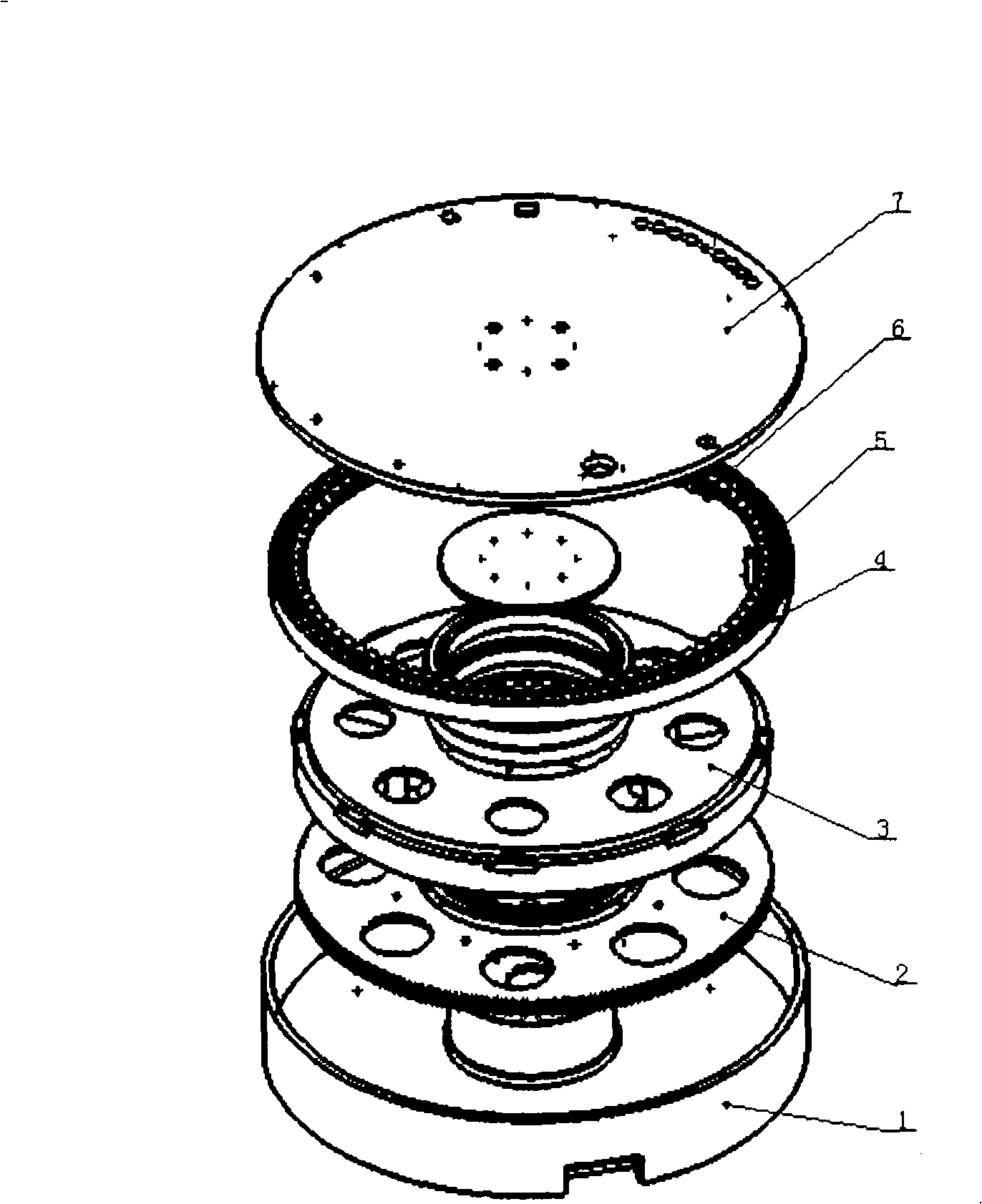
[0008] Such as figure 1 As shown, the reaction disk assembly of the present invention includes: a support seat 1 , a gear disk 2 , a magnetic disk 3 , a reaction disk 4 and a support plate 7 . The gear disc 2, the magnetic disc 3, and the reaction disc 4 are all of a single annular structure and coaxially arranged. The supporting seat 1 is arranged at the bottom of the reaction disk assembly, and is used for fixing the relative position of the reaction disk assembly and adapting to the relative position relationship of the liquid filling needle. The gear plate 2 is arranged above the support base 1 and is driven to rotate by a servo motor. The motor speed is about 600 rpm, and the rotation speed of the gear plate 2 is about 1 rpm. The magnetic disk 3 is arranged on the top of the gear disk 2, driven by the gear disk 2 to rotate through gears, the speed ratio of the pulley is about 1:10, and the magnetic disk 3 is provided with a movable pin 5. The reaction disk 4 is used to ...


PUM


Abstract

The invention relates to a reaction disc assembly, which comprises a bearing seat (1), a gear disc (2), a magnetic disc (3), a reaction disc (4) and a bearing plate (7), wherein the gear disc (2) is driven to rotate by a motor and drives the magnetic disc (3) to rotate through a gear, and the reaction disc assembly is characterized in that the gear disc (2), the magnetic disc (3) and the reaction disc (4) all have a single circular structure respectively and are coaxially arranged.

Description

technical field [0001] The invention relates to a reaction disk assembly, in particular to a reaction disk assembly capable of realizing continuous work. Background technique [0002] The reaction disk assembly in the prior art is usually a whole ring structure, and the overall processing is relatively difficult. In addition, there is an increasing demand for reaction tray assemblies that enable continuous, efficient operation. Contents of the invention [0003] The object of the present invention is to provide a reaction disk assembly which is easy to process and can realize continuous operation. [0004] In order to achieve the purpose of the present invention, the present invention provides a reaction disk assembly, including: a support seat, a gear disk, a magnetic disk, a reaction disk and a support plate, the gear disk is driven by a motor to rotate and drives the disk to rotate through gears, the gear disk, The magnetic disk and the reaction disk are each in a sin...

Claims


Application Information

Patent Timeline
Patent Type & Authority Applications(China)
IPC IPC(8): G01N35/04
Inventor 王志安吴晓东
Owner BEIJING YUANDE BIO MEDICAL ENG
Why Eureka
Try Eureka