Metal plate annular electromagnetic pulse progressive reverse drawing forming method and device

A technology of reverse deep drawing and electromagnetic pulse, which is applied in the field of material plastic forming, can solve problems such as unreasonable stress state, uneven wall thickness distribution, and shallow forming depth, so as to improve the forming limit, overcome cracking defects, reduce energy effect

Inactive Publication Date: 2014-04-16
HUAZHONG UNIV OF SCI & TECH
View PDF7 Cites 16 Cited by
  • Summary
  • Abstract
  • Description
  • Claims
  • Application Information

AI Technical Summary

Problems solved by technology

[0007] In order to solve the problems of unreasonable stress state, existing drawing crack defects, uneven wall thickness distribution and shallow forming depth in the existing deep drawing forming, the present invention proposes a metal sh

Method used


Image

  • Metal plate annular electromagnetic pulse progressive reverse drawing forming method and device
  • Metal plate annular electromagnetic pulse progressive reverse drawing forming method and device
  • Metal plate annular electromagnetic pulse progressive reverse drawing forming method and device

Examples


Embodiment 1

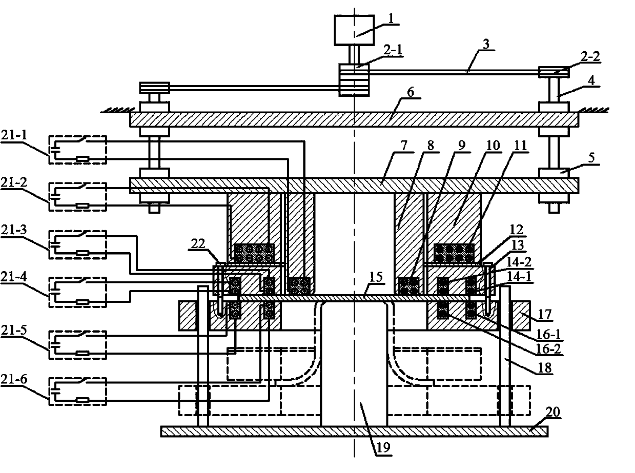
[0068] Such as figure 2 As shown, the present invention provides a ring-shaped electromagnetic pulse progressive reverse drawing forming device for metal sheets, including a die drive mechanism, a die 8, an annular deep-drawing coil 9, a splint drive mechanism, a splint 13, a bracket 17, Guide post 18, punch 19, base 20, screw 22, two booster coil groups and power supply system.

[0069] The die 8 is matched with the punch 19, the ring-shaped deep drawing coil 9 is embedded in the die 8, the guide post 18 and the punch 19 are fixedly installed on the base 20, and the splint 13 is connected with the support by four screws 22 arranged in the circumferential direction. The frame 17 is connected, the bracket 17 is sleeved on the guide post 18, and can slide up and down along the guide post 18; the splint 13 is arranged on the periphery of the die 8; the die 8 is driven by the die drive mechanism, and the The splint 13 is driven by the splint driving mechanism; the blank 15 to be...

Embodiment 2

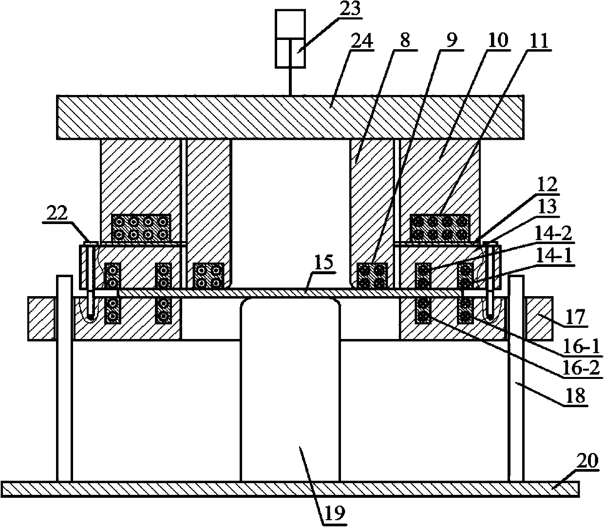
[0078] The die driving mechanism can also be realized by air / hydraulic cylinder 23 and slide block 24, such as image 3 As shown, the die 8 and the push-down coil holder 10 are fixedly installed on the lower surface of the slider 24, and the slider 24 is driven by an air / hydraulic cylinder 23. The structure of other parts and the method of reverse drawing and forming are exactly the same as those in Embodiment 1. The same, and will not repeat the description here.

Embodiment 3

[0080] Using the annular electromagnetic pulse progressive reverse drawing forming device of the metal sheet described in Embodiment 1, the method for performing reverse drawing specifically includes:

[0081] Such as Figure 11a As shown, at first the blank 15 to be formed is placed between the die 8 and the punch 19, and the blank 15 to be formed is positioned at the initial blank position 15-1 at this moment; 3. The transmission of the second pulley 2-2, screw rod 4, and nut 5 exerts downward pressure on the moving beam 7, so that the die 8 and the push-down coil seat 10 follow the moving beam 7 to go down until the bottom of the push-down coil seat 10 just touches To the upper end of the driving piece 12, in preparation for the next step of electromagnetic reverse drawing, when the die 8 is descending, the blank 15 to be formed at the bottom of the die 8 is squeezed into the gap between the die 8 and the punch 19. Gap, reversely draw the sheet material 15 to be formed to ...


PUM


Abstract

The invention provides a metal plate annular electromagnetic pulse progressive reverse drawing forming method. The method includes the steps that a to-be-formed plate is placed between a female die and a male die; the periphery of the female die is provided with a clamping plate, and the periphery of the male die is provided with a supporting frame; pre-forming force is exerted on the to-be-formed plate; electromagnetic force is exerted to push the to-be-formed plate and the clamping plate downwards; electromagnetic force is exerted on the periphery of the to-be-formed plate, and the to-be-formed plate is pushed horizontally towards the center of the female die, so that the to-be-formed plate flows into the female die and reverse drawing forming is achieved; lower pressure is exerted to drive the female die to move downwards, and the to-be-formed plate at the bottom of the female die is squeezed into a gap between the female die and the male die, so that reverse drawing forming of the plate is achieved; reverse drawing and electromagnetic pulse drawing are repeatedly carried out on the female die and the male die until reverse drawing forming is finished. According to the method, forming limits can be substantially increased, and the forming depth of a cylindrical element is increased. The invention further provides a metal plate annular electromagnetic pulse progressive reverse drawing forming device.

Description

technical field [0001] The invention belongs to the field of plastic forming of materials, and in particular relates to a ring-shaped electromagnetic pulse progressive reverse drawing forming method and device for metal plates. Background technique [0002] In the traditional sheet metal deep drawing forming process, in order to avoid the wrinkling of the material, it is necessary to use a blank holder to assist in forming. Such as figure 1 Shown is the stress-strain state of the formed sheet during conventional deep drawing. The flange area is subjected to radial tensile stress and tangential (circumferential) compressive stress, and produces elongation and compression deformation in the radial and tangential directions respectively. The thickness of the plate increases slightly, and the thickness at the outer edge of the flange increases the most. At the rounded corner of the die, in addition to being drawn radially, the material also undergoes plastic bending to reduce ...

Claims


Application Information

Patent Timeline
IPC IPC(8): B21D22/22B21D24/16
Inventor 莫健华方进秀李建军崔晓辉黄亮李奋强
Owner HUAZHONG UNIV OF SCI & TECH
Why Eureka
Try Eureka