Micro structure hard alloy turning tool blade for cutting AISI201

An AISI201, cemented carbide technology, applied in cutting inserts, tools for lathes, turning equipment, etc., can solve problems such as insufficient micro-groove structure design

Pending Publication Date: 2021-05-18
GUIZHOU UNIV
View PDF6 Cites 0 Cited by
  • Summary
  • Abstract
  • Description
  • Claims
  • Application Information

AI Technical Summary

Problems solved by technology

[0005] Although our team achieved the purpose of reducing the cutting temperature and improving the durability by designing micro-grooves in the shape of baseball bats near the cutting edge, these existing micro-groove structures still have deficiencies.

Method used


Image

  • Micro structure hard alloy turning tool blade for cutting AISI201
  • Micro structure hard alloy turning tool blade for cutting AISI201
  • Micro structure hard alloy turning tool blade for cutting AISI201

Examples


Embodiment 1

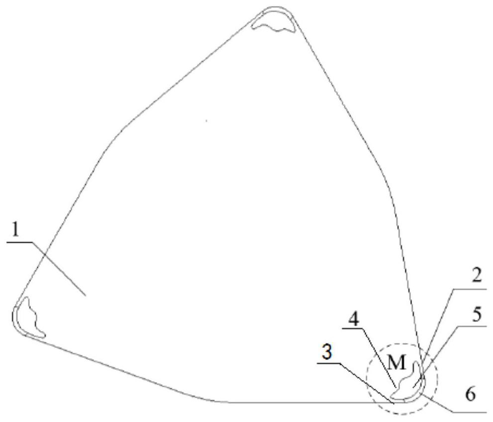
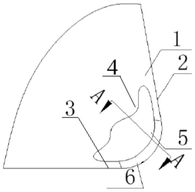
[0043] Embodiment 1: a kind of microstructure cemented carbide turning insert of cutting AISI201, as attached Figure 1-3 shown. Including the rake face 1, the sharp corner of the rake face 1 is a cutting edge 6, one side of the cutting edge 6 is the main cutting edge 2, the other side is the secondary cutting edge 3, and the inner side of the cutting edge 6 is the near region 4 of the cutting edge; The near area 4 of the cutting edge is provided with a micro-groove 5, and the micro-groove 5 is an ingot-shaped structure with asymmetry, overall unequal width and unequal depth; the maximum depth of the micro-groove 5 is 0.35mm; the micro-groove 5 The distance between the edge and the edge of the main cutting edge 2 is 0.15mm; the length of the micro-groove 5 on the main cutting edge 2 side is 3.5mm, and the length on the side of the minor cutting edge 3 is 2.5mm; the maximum width of the micro-groove 5 is 1mm. The connection forms between the outer edge of the micro-groove 5 a...

Embodiment 2

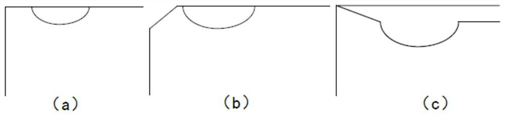
[0044] Embodiment 2: a kind of microstructure cemented carbide turning insert of cutting AISI201, as attached Figure 1-3 shown. Including the rake face 1, the sharp corner of the rake face 1 is a cutting edge 6, one side of the cutting edge 6 is the main cutting edge 2, the other side is the secondary cutting edge 3, and the inner side of the cutting edge 6 is the near region 4 of the cutting edge; The near region 4 of the cutting edge is provided with a microgroove 5, and the microgroove 5 is an ingot-shaped structure with an asymmetrical overall unequal width and unequal depth; the section of the microgroove 5 on the rake face 1 is asymmetrical. Curve type, the bottom surface of the micro-groove 5 is a smooth transition surface; the maximum depth of the micro-groove 5 is 0.25mm; the distance between the edge of the micro-groove 5 and the edge of the main cutting edge 2 is 0.1mm; The length of the side is 2.5mm, and the length of the side close to the minor cutting edge 3 i...

Embodiment 3

[0045] Embodiment 3: a kind of microstructure cemented carbide turning insert of cutting AISI201, as attached Figure 1-3 shown. Including the rake face 1, the sharp corner of the rake face 1 is a cutting edge 6, one side of the cutting edge 6 is the main cutting edge 2, the other side is the secondary cutting edge 3, and the inner side of the cutting edge 6 is the near region 4 of the cutting edge; The near region 4 of the cutting edge is provided with a microgroove 5, and the microgroove 5 is an ingot-shaped structure with an asymmetrical overall unequal width and unequal depth; the section of the microgroove 5 on the rake face 1 is asymmetrical. Curve type, the bottom surface of the micro groove 5 is a smooth transition surface; the maximum depth of the micro groove 5 is 0.50mm; the distance between the edge of the micro groove 5 and the edge of the main cutting edge 2 is 0.18mm; the micro groove 5 is close to the main cutting edge 2- The length of the side is 3.7mm, the l...


PUM


Abstract

The invention discloses a micro structure hard alloy turning tool blade for cutting AISI201. The micro structure hard alloy turning tool blade comprises a rake face, wherein a cutting edge is arranged at the sharp corner of the rake face, one side of the cutting edge is a main cutting edge, the other side of the cutting edge is a tool mirror cutting edge, and the inner side of the cutting edge is a cutting edge near area; and a microgroove is arranged in the near area of the cutting edge, and the microgroove is of an asymmetric shoe-shaped gold ingot-shaped structure with unequal width and unequal depth on the whole. The blade has the characteristics that the near-field cutting temperature reduction effect of the cutting edge is better, the durability of the blade is higher, and the service life is longer.

Description

technical field [0001] The invention relates to an alloy turning blade, in particular to a microstructure hard alloy turning blade for cutting AISI201. Background technique [0002] Cutting is the most important product processing method in the manufacturing industry. With the continuous advancement of cutting technology, in the processing of products such as AISI201 alloy materials, the cutting precision is gradually getting higher and higher, and the quality and service life of processed products are constantly improving. There is even a phenomenon of cutting instead of grinding. In the cutting process, the cutting edge is the main part to remove material, and the working environment of the cutting edge and the rake face area near the cutting edge is the worst. The durability, but also reduce the cutting quality. [0003] The structure of the insert is directly related to the durability of the tool, the efficiency and quality of the machining, so the reasonable design of...

Claims


Application Information

Patent Timeline
Patent Type & Authority Applications(China)
IPC IPC(8): B23B27/00
CPCB23B27/00B23B27/005B23B2222/28B23B2200/04
Inventor 吴锦行何林周滔杜飞龙田鹏飞邹子川杨肖委吴艳英张秀华
Owner GUIZHOU UNIV
Why Eureka
Try Eureka