
Metal pouring device and pouring method

A metal casting and hydraulic cylinder technology, applied in the field of metal casting, can solve the problems of increasing labor costs, product surface damage, affecting product yield, etc., and achieve the effect of improving yield

Active Publication Date: 2014-04-16
JOMOO KITCHEN & BATHROOM
View PDF5 Cites 5 Cited by
  • Summary
  • Abstract
  • Description
  • Claims
  • Application Information

AI Technical Summary

Problems solved by technology

However, in the process of separating the cavity from the product, since the cavity and the product are closely combined, it is easy to cause damage to the surface of the product during the removal process, thereby affecting the yield of the product
The product is repaired twice, which increases the labor cost

Method used


Image

  • Metal pouring device and pouring method
  • Metal pouring device and pouring method
  • Metal pouring device and pouring method

Examples


Embodiment Construction

[0044] In order to make the technical problems, technical solutions and beneficial effects to be solved by the present invention clearer and clearer, the present invention will be further described in detail below in conjunction with the accompanying drawings and embodiments. It should be understood that the specific embodiments described here are only used to explain the present invention, not to limit the present invention.

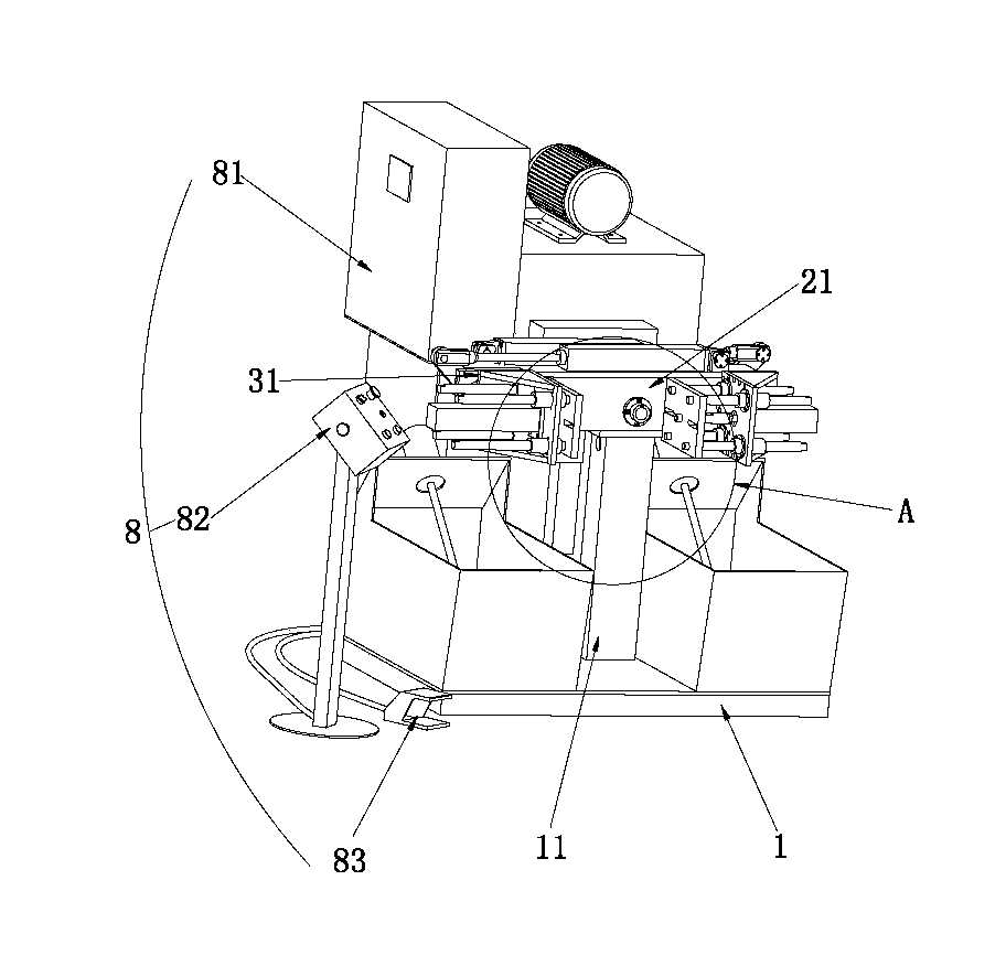
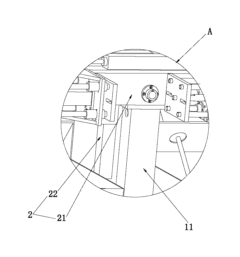
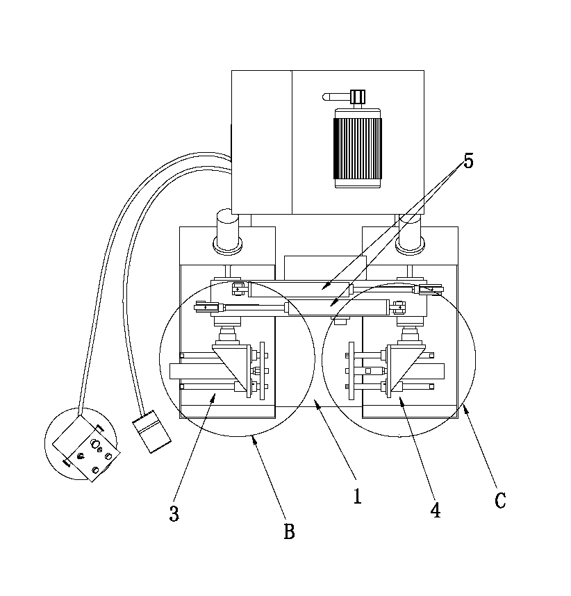
[0045] Such as figure 1 , figure 2 , image 3 As shown, the metal pouring device of the present invention includes a machine platform 1 , a crossbeam assembly 2 , a left mold assembly 3 , a right mold assembly 4 , and a mold group rotating hydraulic cylinder 5 . Wherein, a support column 11 is provided on the machine platform 1 , and the support column 11 extends upward from the bottom surface of the machine platform 1 . The beam assembly 2 includes a beam 21, a first hydraulic cylinder 22, and a transmission mechanism 23 (such as Figure 6 , Fig...


PUM


Abstract

The invention discloses a metal pouring device which comprises a machine table. A horizontal beam component comprises a horizontal beam, a first hydraulic cylinder and a transmission mechanism. The first hydraulic cylinder is arranged on the side wall of a supporting column and drives the horizontal beam to rotate through the transmission mechanism. A left mould component comprises a left arm, a left template and a second hydraulic cylinder which is arranged on the left arm and is used for pushing the left template to move. A right mould component comprises a right arm, a right template and a third hydraulic cylinder. The right template is fixedly connected to a piston rod of the third hydraulic cylinder which is arranged on the right arm and is used for pushing the right template to move. The two ends of a mould set rotating hydraulic cylinder are connected with the left arm of the left mould component and the right arm of the right mould component respectively. The mould set rotating hydraulic cylinder moves in a stretching mode to drive the left arm and the right arm to rotate. According to the scheme, the left mould component and the right mould component can be separated easily, and accordingly separating of a metal product and a mould cannot damage the surface of the metal product.

Description

technical field [0001] The invention relates to the field of metal casting, in particular to a metal pouring device and a pouring method with simple structure and good stability. Background technique [0002] Metal casting is a conventional technology in the foundry industry. For example, faucets and metal pendants in the bathroom industry are all made of metal casting. In the traditional metal pouring process, the cavity with the complete shape of the product is generally made first, and then liquid metal liquid is injected into the cavity. After the liquid metal liquid cools down, the cavity is separated from the product to obtain the product. . However, in the process of separating the cavity from the product, since the cavity and the product are closely combined, it is easy to cause damage to the surface of the product during the removal process, thereby affecting the yield of the product. The product is repaired twice, which increases the labor cost. Contents of the...

Claims


Application Information

Patent Timeline
IPC IPC(8): B22D23/00
Inventor 林孝发林孝山蒋东照郑英龙
Owner JOMOO KITCHEN & BATHROOM
Learn More