Circular tube cutting-off device

A cutting device and a technology for round pipes, applied in the field of round pipe processing, can solve the problems of inability to cut spiral welded pipes, movement of column 15, unusability, etc., and achieve the effects of being conducive to popularization and use, convenient and reliable operation, and improving cutting quality

Inactive Publication Date: 2014-04-16
TAIYUAN HEAVY IND
View PDF8 Cites 9 Cited by
  • Summary
  • Abstract
  • Description
  • Claims
  • Application Information

AI Technical Summary

Problems solved by technology

[0003] In the above structure, since the column 15 cannot move along the trolley 12, when encountering a spiral welded pipe 18 with a small diameter, it cannot be used
Moreover, due to structural limitations, the torch 16 can only passively cut according to the rotational speed of the spiral welded pipe 17, and cannot select the optimal cutting speed and feed rate for the diameter and wall thickness of the spiral welded pipe. When the thickness exceeds a certain value, the cutting quality of the cutting device will be affected, and the spiral welded pipe 17 cannot be cut even if the cross section is irregular. The spiral welded pipe 17 must be trimmed twice, and sometimes even the production will stop, which seriously affects the production of the spiral welded pipe 17. quality and efficiency

Method used


Image

  • Circular tube cutting-off device
  • Circular tube cutting-off device
  • Circular tube cutting-off device

Examples


Embodiment Construction

[0028] Typical embodiments embodying the features and advantages of the present invention will be described in detail in the following description. It should be understood that the present invention is capable of various changes in different embodiments without departing from the scope of the present invention, and that the description and drawings therein are illustrative in nature and not limiting. this invention.

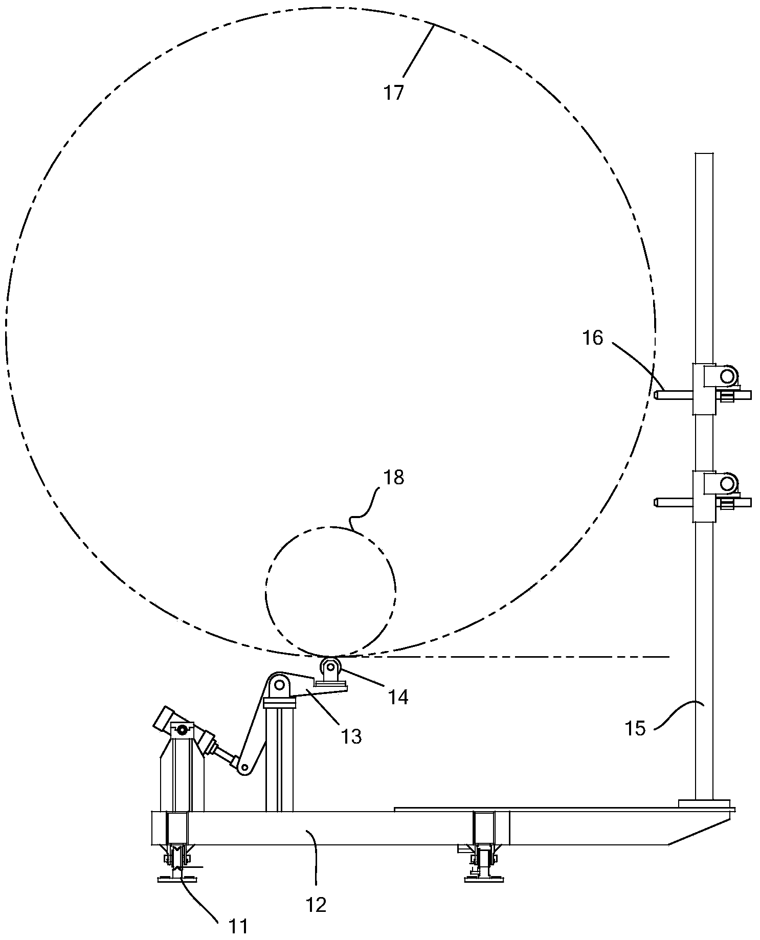
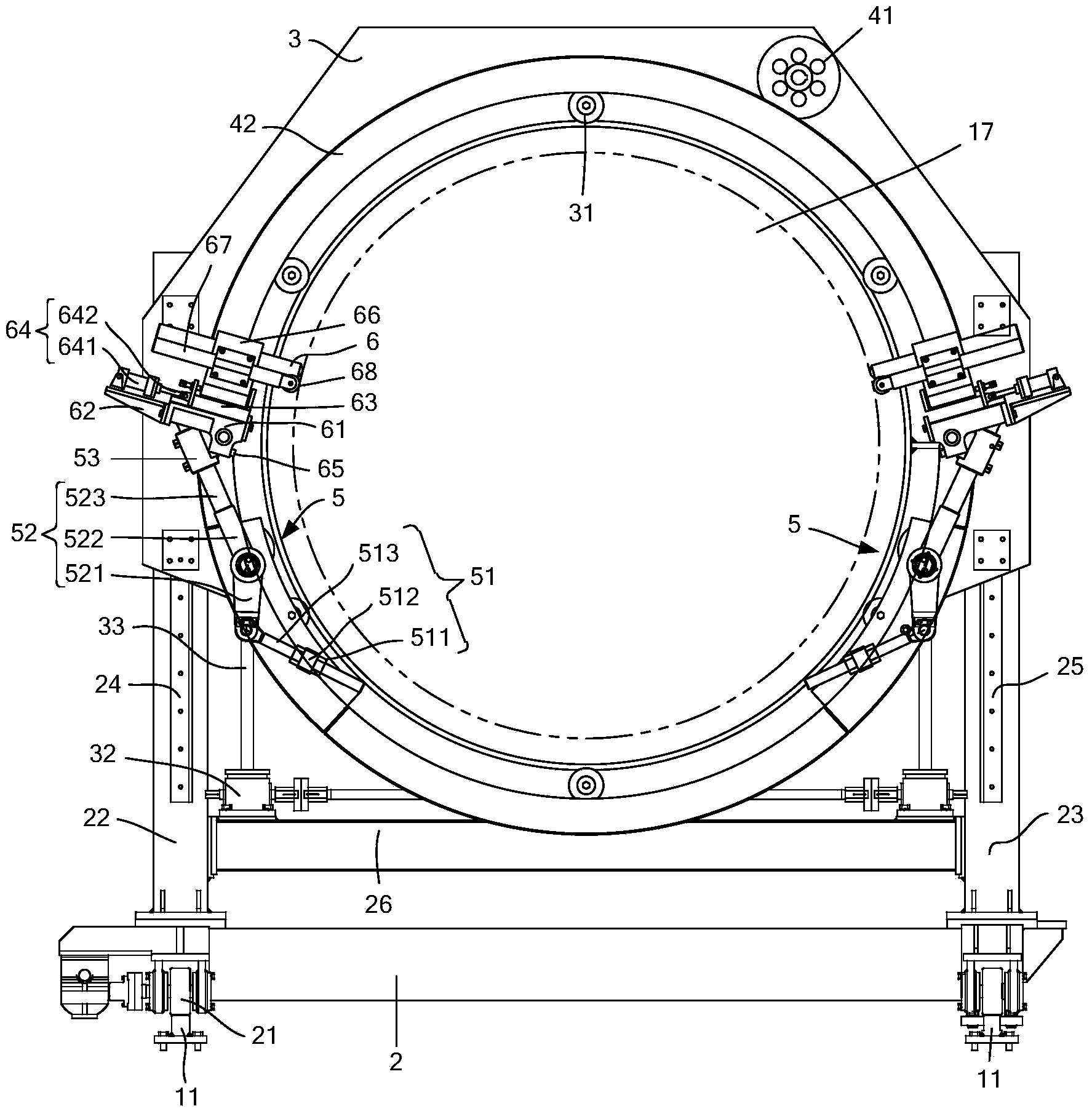
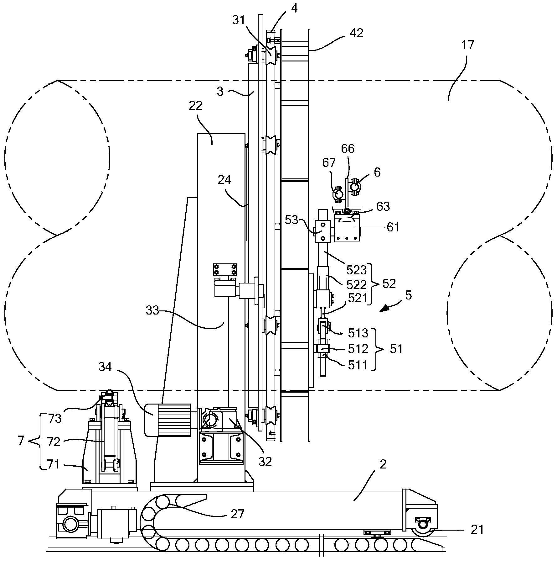
[0029] Such as figure 2 , image 3 with Figure 4 As shown, the round pipe cutting device of the present invention includes guide rail 11, trolley 2, top wheel device 7, slide seat 3, ring gear 4, linkage mechanism 5 or 8, push rod 67 and torch 6. In the following specific embodiments, the round pipe against which is the spiral welded pipe 17 or 18 .

[0030] Wherein, there are two guide rails 11, which are arranged in parallel, which is no different from the existing structure.

[0031] Roller 21 is installed on the bottom of dolly 2, and this roller 21 ma...


PUM


Abstract

The invention discloses a circular tube cutting-off device which comprises a trolley, a sliding base, a gear ring and a connecting rod mechanism. The lower portion of the trolley is matched with two guiding rails through idler wheels, wherein the guiding rails are arranged in parallel. The upper portion of the trolley is symmetrically provided with two stand columns. The trolley is further provided with a top wheel device, the height of the top wheel device can be adjusted, and the sliding base is installed on the stand columns in a height-adjustable mode. A circular hole where a circular tube penetrates is formed in the sliding base. The gear ring can be installed on the sliding base in a rotating mode and is concentric with the circular hole in the sliding base. The connecting rod mechanism is symmetrically installed on the gear ring. A cutting gun for cutting the circular tube is installed at the end of the connecting rod mechanism, and corresponds to the circular tube. The top wheel device abuts against the circular tube. The position of the sliding base on the stand columns is adjusted so as to enable the axis of the circular tube to penetrate through the circular hole and the circle center of the gear ring. According to the circular tube cutting-off device, the gear ring is adopted and can rotate, so that the cutting gun can be driven by the connecting rod mechanism to rotate; the cutting speed and feeding amount of the cutting gun can be determined according to actual requirements, so that the cutting speed and quality of the circular tube are improved.

Description

technical field [0001] The present invention relates to the processing of round pipes, especially related to the device structure for cutting round pipes in the processing of round pipes, especially the cutting of spiral welded pipes. Background technique [0002] At present, the spiral welded pipe needs to be cut, and the structure of the existing spiral welded pipe cutting device is as follows: figure 1 As shown, the existing spiral welded pipe cutting device includes parts such as guide rail 11, dolly 12, support member 13, top wheel 14, column 15 and torch 16. During work, the trolley 12 moves along the guide rail 11 following the spiral welded pipe 17, the top wheel 14 supports the spiral welded pipe 17, and the torch 16 can move up and down along the column 15 to find a suitable cutting position. [0003] In the above structure, since the column 15 cannot move along the trolley 12, it cannot be used when encountering a spiral welded pipe 18 with a small diameter. Mor...

Claims


Application Information

Patent Timeline
Patent Type & Authority Applications(China)
IPC IPC(8): B23K10/00
CPCB23K10/00B23K2101/06
Inventor 曹一兵曹益忠聂建辉
Owner TAIYUAN HEAVY IND
Why Eureka
Try Eureka