Sliding table

A sliding table and sliding block technology, which is applied in the direction of large fixed members, metal processing machinery parts, metal processing, etc., can solve the problems of unfavorable operation, unfavorable sliding table placement, large length and area occupied by the sliding table, etc., to achieve easy operation , to avoid taking up extra space, the effect of compact structure

Inactive Publication Date: 2014-04-16
四川成焊宝玛焊接装备工程有限公司
View PDF5 Cites 3 Cited by
  • Summary
  • Abstract
  • Description
  • Claims
  • Application Information

AI Technical Summary

Problems solved by technology

However, when the cylinder and the piston rod are longer, the length and area occupied by the entire slide table are larger, which is not conducive to the placement of the slide table, nor to the actual operation.

Method used


Image

  • Sliding table

Examples


Embodiment Construction

[0010] The present invention will be further described below in conjunction with the accompanying drawings and embodiments.

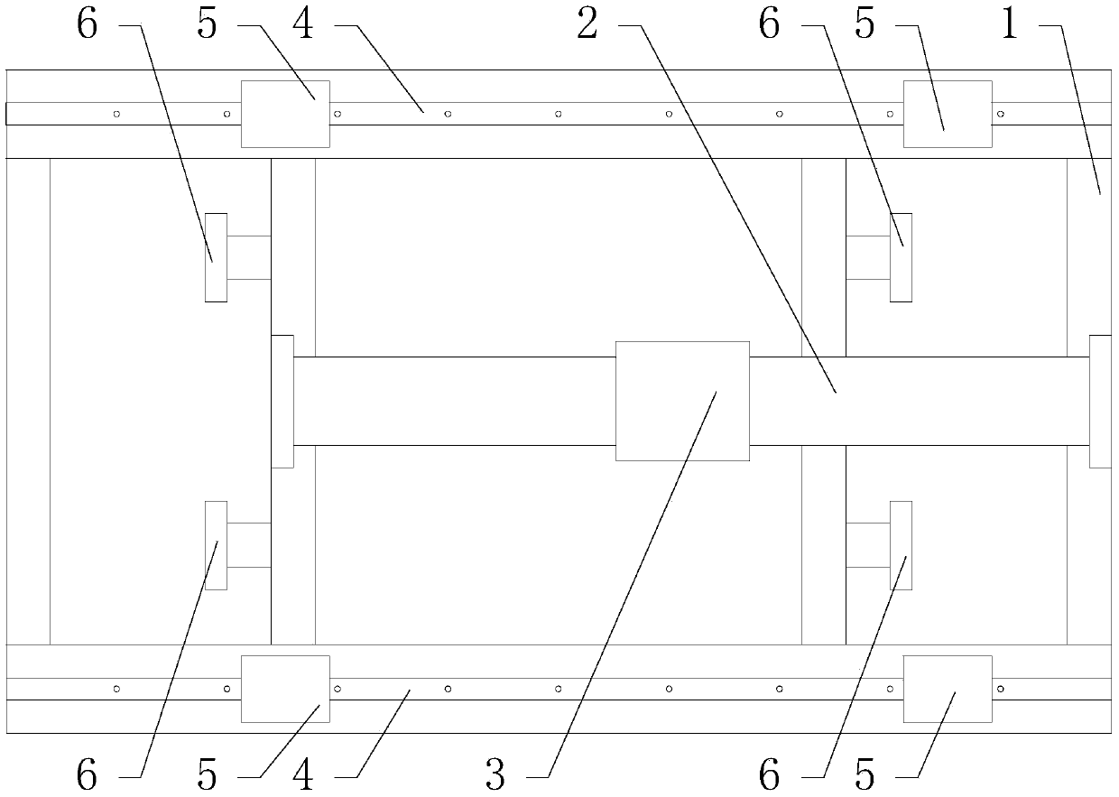
[0011] Such as figure 1 As shown, the slide table of the present invention includes a base 1, a magnetic cylinder 2 is arranged in the base, and a magnetic plate 3 slidably connected with the magnetic cylinder 2 is arranged above the piston of the magnetic cylinder 2. Since the magnetic cylinder 2 does not need to use an external push rod, the piston equipped with a magnetic ring can also drive the magnetic plate 3 to move. Therefore, when working, the magnetic switch on the cylinder can control the reciprocating movement of the piston to drive the magnetic plate above the piston. The component platform mounted above the board 3 and the magnetic board 3 moves.

[0012] In order to improve the efficiency of the moving components, two guide rails 4 parallel to the magnetic cylinder 2 are provided on the base 1 , and each guide rail 4 is provided with two...


PUM


Abstract

The invention discloses an auxiliary device for machining which is mainly used for moving and positioning a sliding table needing to be machined. The sliding table has the advantages of being compact in structure and saving space. The sliding table comprises a base, a magnetic air cylinder is arranged in the base, and a magnetic plate connected with the magnetic air cylinder in a sliding mode is arranged above a piston of the magnetic air cylinder. When the sliding table works, the piston provided with a magnetic ring is controlled by a magnetic switch on the cylinder barrel to make reciprocating motion, so that the magnetic plate above the piston and a component platform carried on the magnetic plate are driven to move. The sliding table is more reasonable and compact in structure, no excess space is occupied any longer except for the base, and meanwhile the sliding table is more convenient to operate and suitable for various kinds of machining.

Description

technical field [0001] The invention relates to a machining aid, in particular a slide table for moving and positioning components. Background technique [0002] At present, when a sliding table is used as a device for moving and positioning components, the components on the sliding table are generally driven by a cylinder with a rod to move. In order to adapt to various working environments, the slide table is generally larger and longer, which leads to the fact that its cylinder and piston rod must also have a longer length to meet the demand. However, when the cylinder and the piston rod are longer, the length and area occupied by the entire slide table are larger, which is not conducive to the placement of the slide table, nor to the actual operation. Contents of the invention [0003] The technical problem to be solved by the present invention is to provide a volume-saving and compact slide table. [0004] The technical solution adopted by the present invention to s...

Claims


Application Information

Patent Timeline
IPC IPC(8): B23Q7/00
CPCB23Q5/38B23Q1/28B23Q1/30B23Q5/52B23Q2705/12
Inventor 于成哉吴红成古湘蓉
Owner 四川成焊宝玛焊接装备工程有限公司
Why Eureka
Try Eureka