Precise surface polishing device and transmission device for precise surface polishing

A technology of precision polishing and transmission device, which is applied in the direction of grinding drive device, grinding/polishing equipment, grinding machine parts, etc. , Reduce the mechanical failure rate and maintenance cost, and improve the effect of polishing speed

Active Publication Date: 2014-04-16
山佳卫 +2
View PDF8 Cites 0 Cited by
  • Summary
  • Abstract
  • Description
  • Claims
  • Application Information

AI Technical Summary

Problems solved by technology

[0005] The technical problem to be solved by the present invention is how to solve the problem of limited rotational speed and single movement mode of polishing equipment

Method used


Image

  • Precise surface polishing device and transmission device for precise surface polishing
  • Precise surface polishing device and transmission device for precise surface polishing
  • Precise surface polishing device and transmission device for precise surface polishing

Examples


Embodiment 1

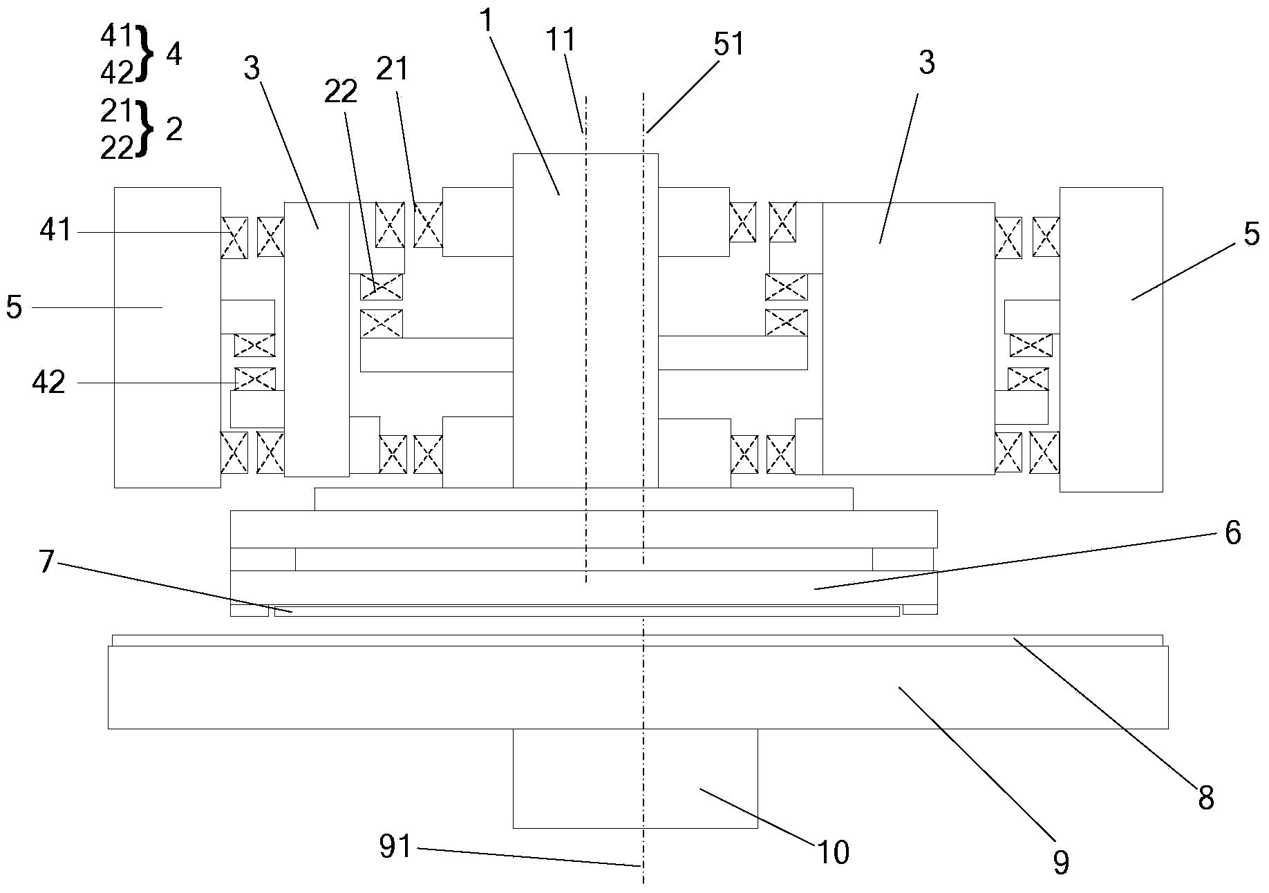
[0030] Please refer to figure 1 This embodiment provides a transmission device for surface precision polishing to drive a processing mechanism to precisely polish a processing object, including a stator mechanism 5, a rotor mechanism 3, and a pendulum mechanism 1. The stator mechanism 5 and the rotor mechanism The magnetic levitation connection is realized between 3, and the rotor mechanism 3 rotates around the axis of the stator mechanism 5 through magnetic levitation. In this embodiment, the rotor mechanism 3 and the stator mechanism 5 have the same axis. Rotating around the axis 51 of the stator mechanism 5, the pendulum mechanism 1 and the rotor mechanism 3 are connected by magnetic levitation, and the pendulum mechanism 1 rotates on its own axis relative to the rotor mechanism 3 through magnetic levitation, that is, around The rotation axis 11 of the pendulum mechanism 1 rotates, the rotation axis 51 of the rotor mechanism 3 and the rotation axis 11 of the pendulum mechanis...

Embodiment 2

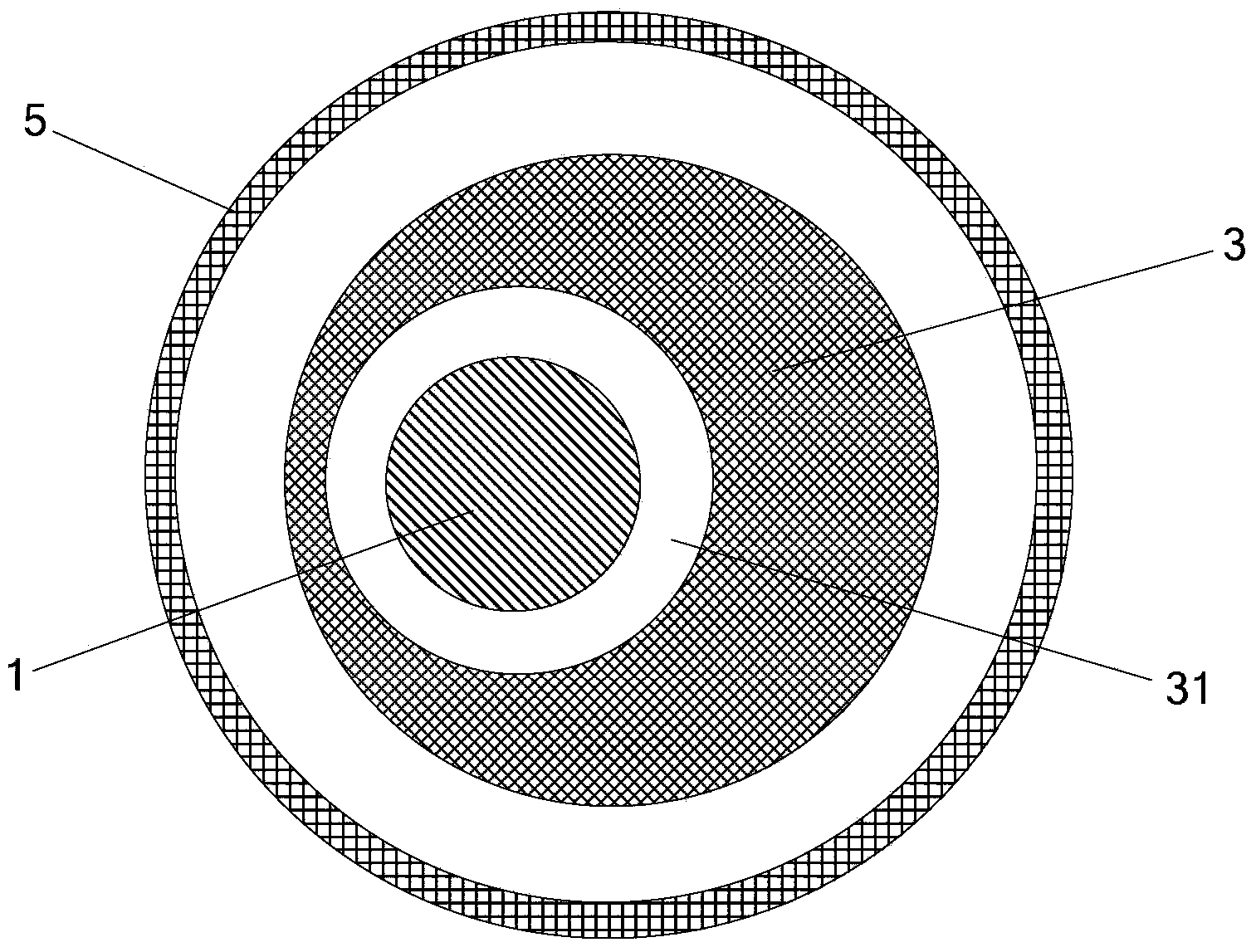
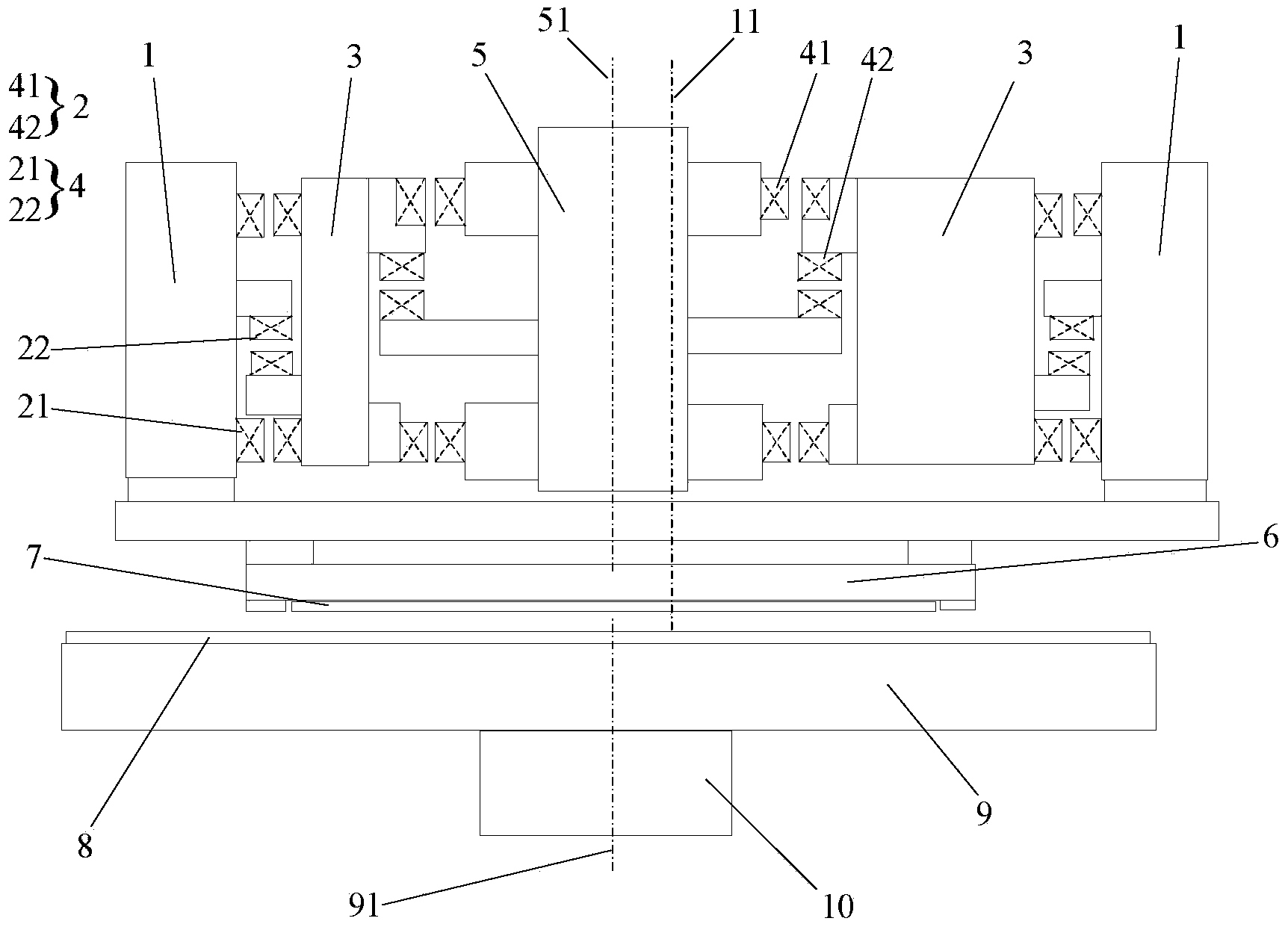
[0044] Please refer to image 3 The difference between this embodiment and the first embodiment is that the rotor mechanism 3 is located inside the pendulum mechanism 1, and the stator mechanism 5 is located inside the rotor mechanism 3. Specifically, please refer to Figure 4 , The rotor mechanism 3 is a cylindrical structure, the rotor mechanism 3 is provided with a cylindrical hole 31, the hole 31 penetrates both ends of the rotor mechanism 3, and the axis of the hole 31 is parallel to the The axis of the rotor mechanism 3 does not overlap. In this embodiment, the stator mechanism 5 is arranged in the hole 31. In addition, other technical features of Embodiment 1 can all be applied to Embodiment 3, and this embodiment will not be repeated.

Embodiment 3

[0046] The difference between this embodiment and embodiment 1 is: please refer to Figure 5 with Image 6 The rotor mechanism 3 is a crankshaft structure, and the rotor mechanism 3 is connected to the stator mechanism 5 and the pendulum mechanism 1 through two shaft pins 301 on the crankshaft structure, and the two shaft pins 301 on the crankshaft structure respectively pass The magnetic suspension is connected with the stator mechanism and the pendulum mechanism. Furthermore, the eccentric double rotation similar to embodiment 1 is realized, and the technical effect similar to embodiment 1 is finally realized. This embodiment only lists another specific structure of the rotor mechanism 3, the stator mechanism 5 and the pendulum mechanism 1. The other technical features of Embodiment 1 can also be applied to Embodiment 3. For example, in this embodiment, the shaft pin 301 is also provided with the electromagnetic bearing assembly listed in Embodiment 1. For other features, this...


PUM


Abstract

The invention provides a precise surface polishing device and a transmission device for precise surface polishing. The transmission device for precise surface polishing is used for driving a machining mechanism to precisely polish a machined object. The transmission device comprises a stator mechanism, a rotor mechanism and a swing mechanism, wherein the rotor mechanism rotates around the axis of the stator mechanism; the swing mechanism is connected with the rotor mechanism by virtue of magnetic suspension; the swing mechanism rotates relative to the rotor mechanism around the axis of the swing mechanism by virtue of magnetic suspension; the rotating axis of the swing mechanism rotates around the rotating axis of the rotor mechanism; the swing mechanism is connected with the machining mechanism. On one hand, an ultrahigh rotating speed becomes possible and the mechanical fault rate and the maintenance cost are reduced to the maximum extent by virtue of introducing a magnetic suspension technology, and on the other hand, the problem of single motion way is solved by utilizing the dual eccentric rotations among the stator mechanism, the rotor mechanism and the swing mechanism.

Description

Technical field [0001] The invention relates to the field of mechanical processing, in particular to a surface precision polishing device and a transmission device for surface precision polishing. Background technique [0002] Polishing refers to the use of mechanical, chemical or electrochemical effects to reduce the surface roughness of the workpiece to obtain a bright, smooth surface. During polishing, flexible polishing tools and abrasive particles or other polishing media are often used to modify the surface of the workpiece. Polishing cannot improve the dimensional accuracy or geometric accuracy of the workpiece, but aims to obtain a smooth surface or mirror gloss, and sometimes it is also used to eliminate gloss (matting). Further, with the development of technology, in many fields, the requirements for the precision of polishing are getting higher and higher, which has led to the rapid development of the field of precision polishing. Among them, the production and progre...

Claims


Application Information

Patent Timeline
Patent Type & Authority Applications(China)
IPC IPC(8): B24B47/12
CPCB24B47/16
Inventor 山佳卫冯建国山佳逸峡
Owner 山佳卫
Why Eureka
Try Eureka