System and method for delivering spark to an engine

An engine, spark technology, applied in the direction of engine components, engine ignition, machine/engine, etc., can solve the problems of increasing controller output and the number of wires, increasing system cost, complexity and assembly time, etc., to reduce assembly time, reduce Effects of ignition system cost, reduced wiring complexity

Active Publication Date: 2014-04-16
FORD GLOBAL TECH LLC
View PDF5 Cites 7 Cited by
  • Summary
  • Abstract
  • Description
  • Claims
  • Application Information

AI Technical Summary

Problems solved by technology

The two ignition coils can be charged and/or discharged at different times to increase spark duration and energy, but operating two ignition coils at different times for each spark plug can significan

Method used


Image

  • System and method for delivering spark to an engine
  • System and method for delivering spark to an engine
  • System and method for delivering spark to an engine

Examples


Embodiment Construction

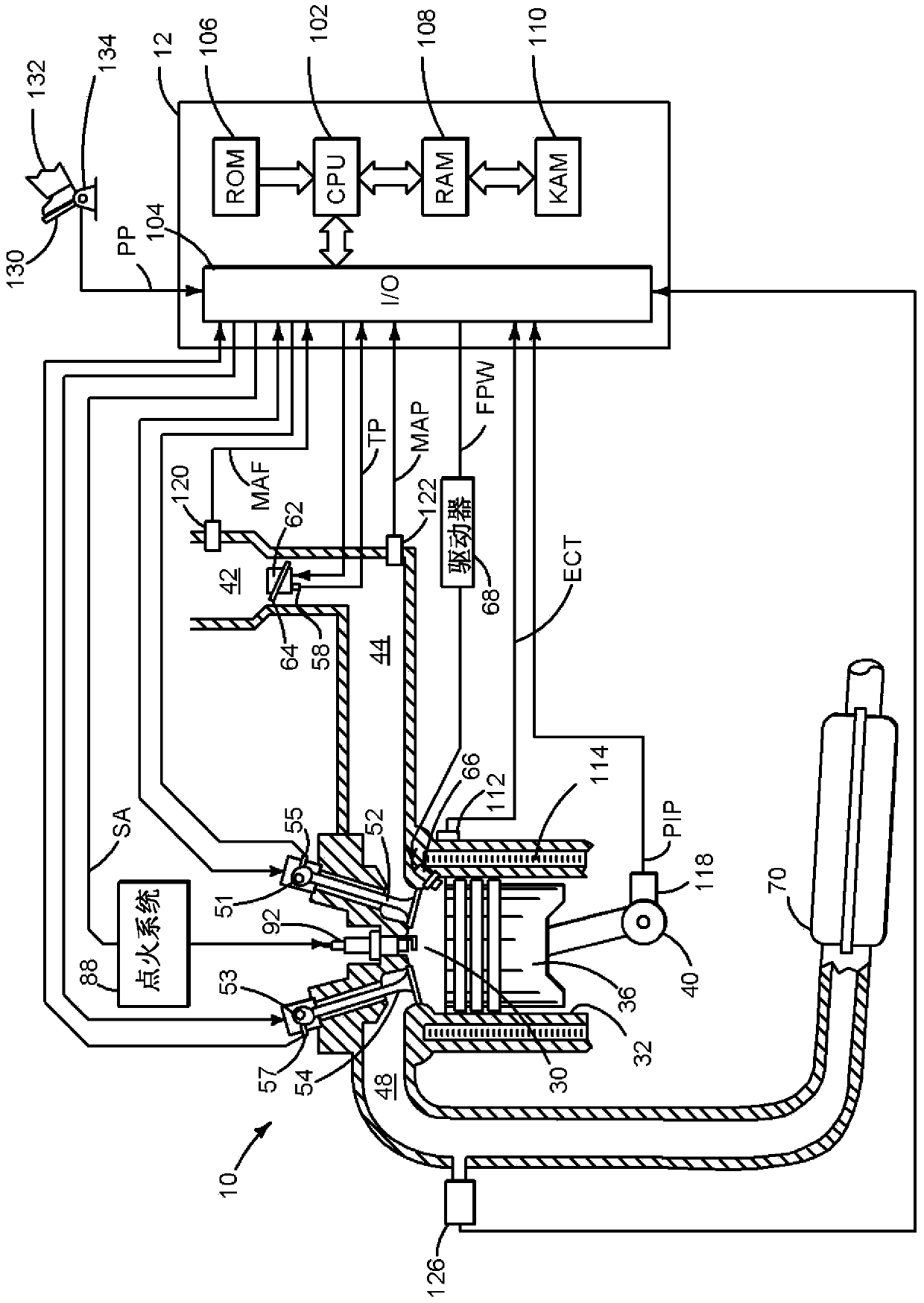
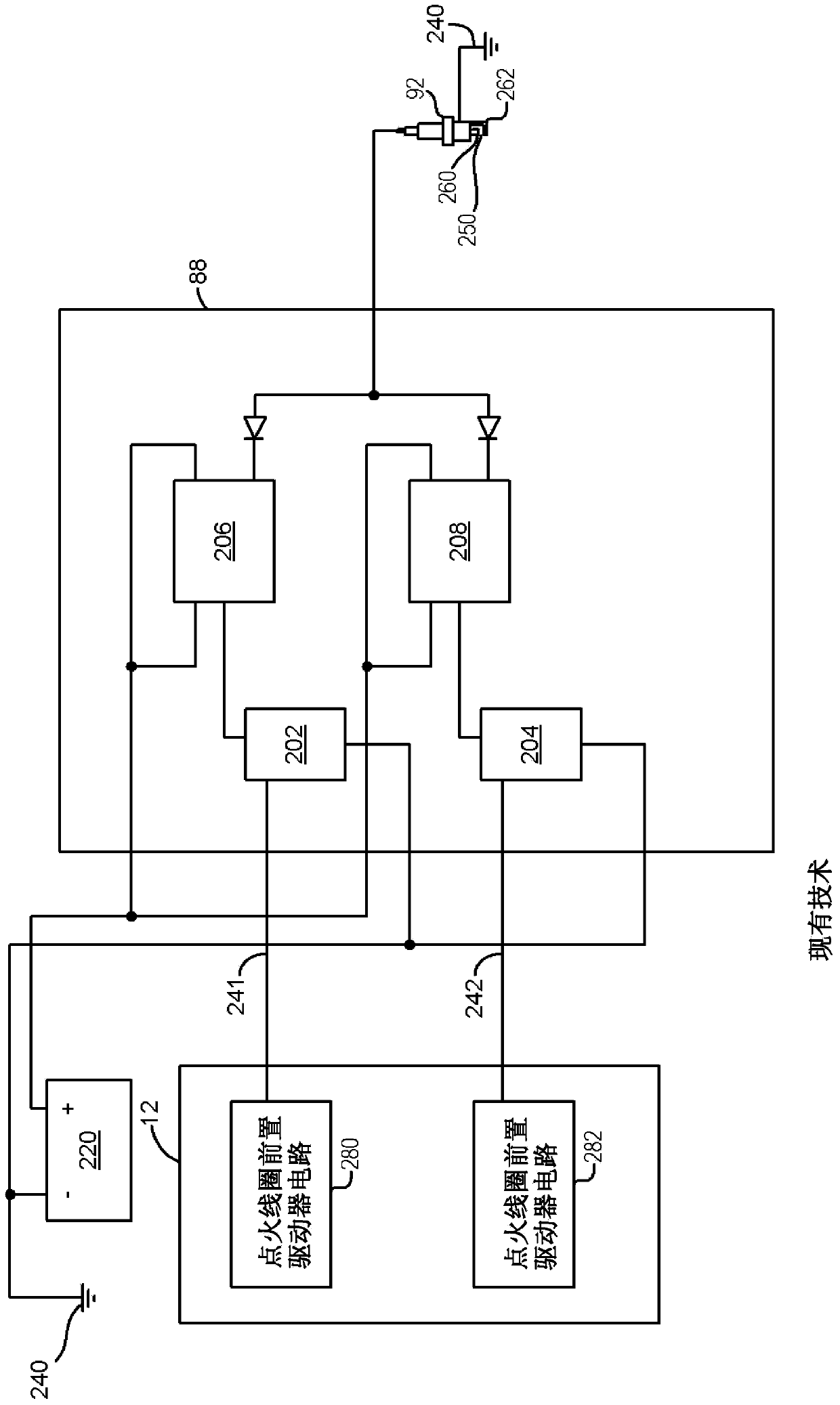
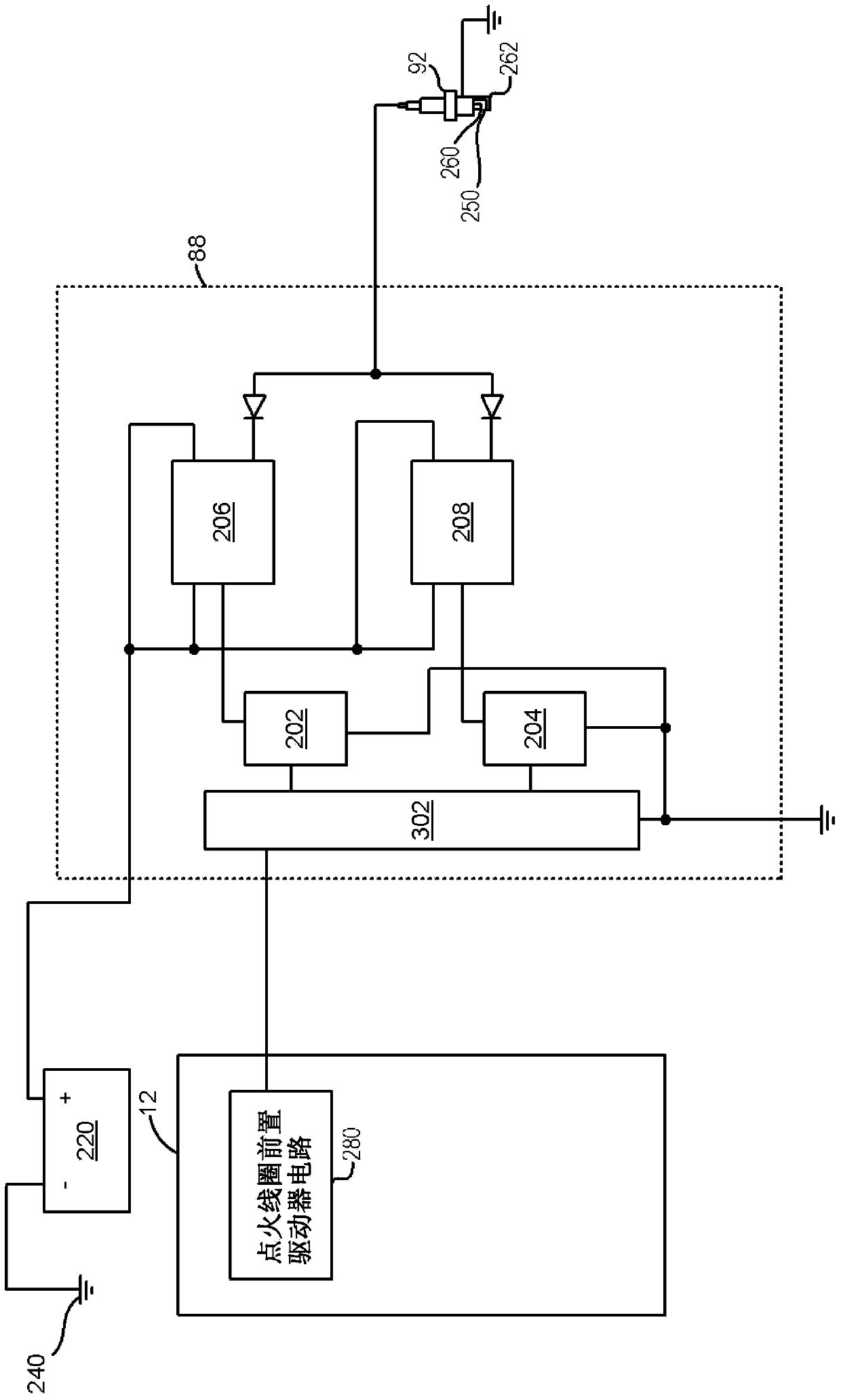
[0032] This specification relates to spark plugs for supplying energy to spark ignition engines. In one non-limiting example, the control signal is supplied via a single wire. The two coils may respectively operate at different times in response to the control signal. Thus, instead of two wires supplying control signals to both ignition coils, a single wire can be used to perform the same function. In this way, the number of controller outputs can be reduced. Additionally, fewer wires can be used within the system compared to other multi-coil systems. figure 1 , image 3 with Figure 4 An example ignition system is shown. figure 2 A prior art ignition system is shown. figure 1 , image 3 with Figure 4 The system can provide Figure 5 with Image 6 Spark energy shown in . Figure 7 with Figure 8 Example ignition system control signals are shown. At last, Figure 9 An example method of powering a single spark plug through two ignition coils is shown.

[0033] r...


PUM


Abstract

A system and method for delivering spark to an engine is disclosed. In one example, a single conductor carries a spark signal that is indicative of a desired spark advance for a plurality of ignition coils. The system and method may reduce wiring complexity for spark plugs that are supplied energy via two ignition coils.

Description

[0001] Cross References to Related Applications [0002] This application claims priority to US Provisional Patent Application No. 61 / 714,058, filed October 15, 2012, the entire contents of which are hereby incorporated by reference for all purposes. technical field [0003] The present application relates to systems and methods for delivering spark to a spark ignition engine. The system and method may be particularly beneficial for engines operating lean or dilute mixtures. Background technique [0004] The engine may be operated with a lean air-fuel mixture or a diluted air-fuel mixture (eg, through exhaust gas recirculation (EGR)) to improve engine fuel economy and / or emissions. However, combustion stability may be reduced when the engine is operated with a lean or dilute mixture. One way to improve the combustion stability of an engine operating with a lean air-fuel mixture is to increase spark energy. Spark energy can be increased by increasing the inductance of the ...

Claims


Application Information

Patent Timeline
IPC IPC(8): F02P3/04
CPCH01T15/00F02P3/04F02P3/045F02P3/0456
Inventor G·J·胡伯茨曲秋平M·D·切卡拉
Owner FORD GLOBAL TECH LLC
Why Eureka
Try Eureka