Whole-stamping retainer structure for tapered roller bearings

A technology for tapered roller bearings and cages, applied to bearing components, shafts and bearings, mechanical equipment, etc., can solve the problems of low overall quality of cages, achieve the effects of improving stamping process performance, stiffness, and stamping performance

Inactive Publication Date: 2014-04-16
LUOYANG YISONG PRECISION BEARING TECH DEV
View PDF7 Cites 8 Cited by
  • Summary
  • Abstract
  • Description
  • Claims
  • Application Information

AI Technical Summary

Problems solved by technology

Realize the full stamping method to manufacture the cage and save materials, and use the innovative tapered roller bearing cage to solve the problem in the existing technology that the overall quality of the cage is low due to poor manufacturability in punching thick plates. The processing method of the new structure cage

Method used


Image

  • Whole-stamping retainer structure for tapered roller bearings
  • Whole-stamping retainer structure for tapered roller bearings
  • Whole-stamping retainer structure for tapered roller bearings

Examples


Embodiment Construction

[0064] In order to further explain the technical means and effects of the present invention to achieve the intended purpose of the invention, the following is a detailed description of the structure of a fully stamped cage for tapered roller bearings proposed according to the present invention in conjunction with the accompanying drawings and preferred embodiments. Embodiments, structures, features and effects thereof are described in detail below.

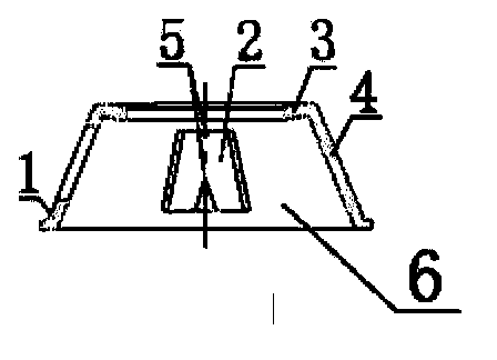
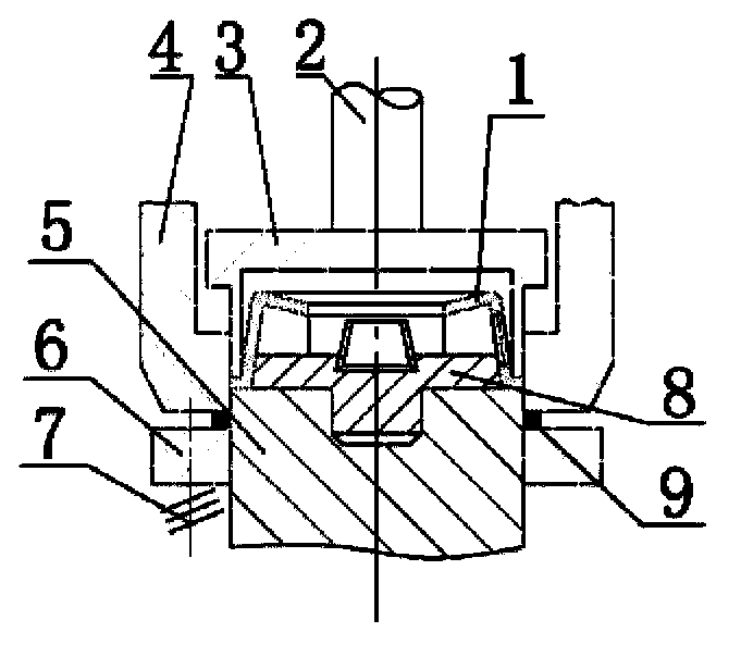
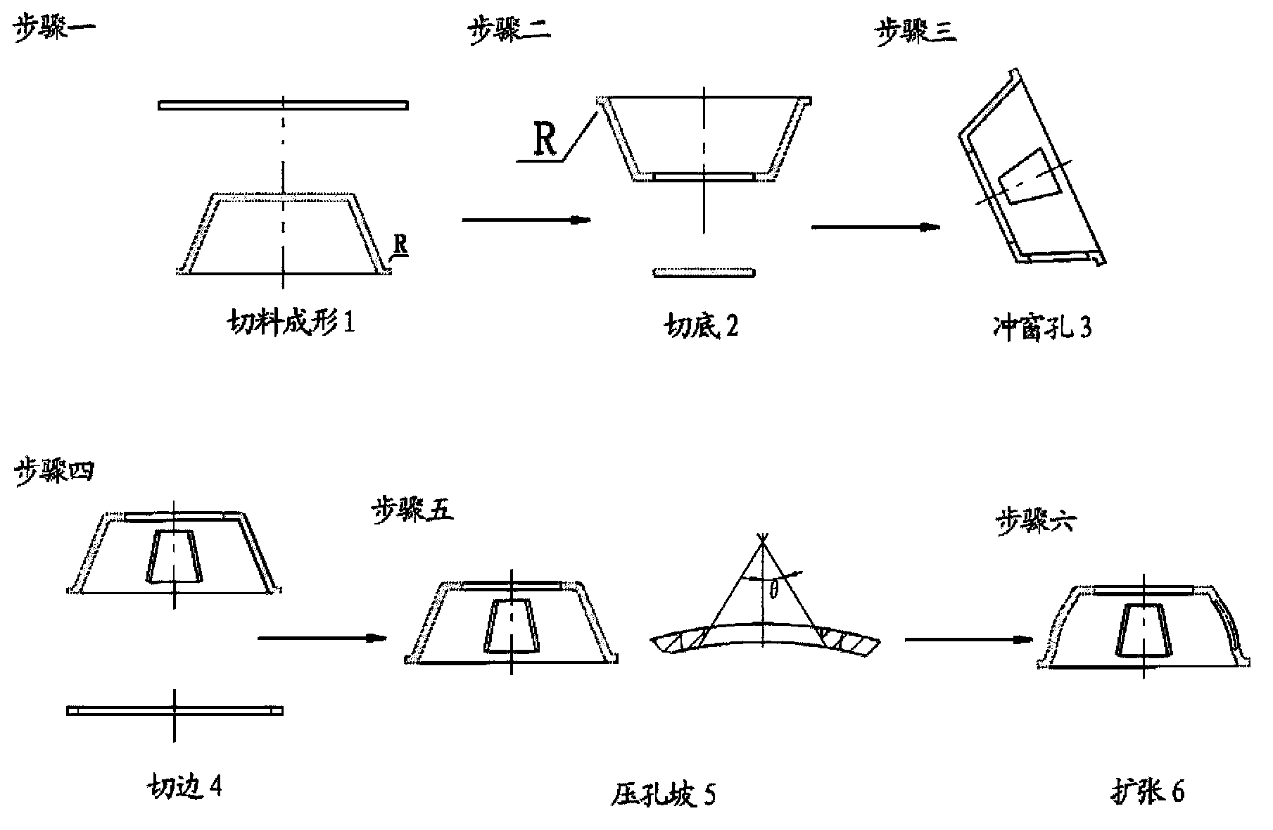
[0065] see figure 1 , figure 2 and image 3 as shown, figure 1 It is a structural schematic diagram of a fully stamped cage for tapered roller bearings. figure 2 It is a schematic diagram of a full stamping cage trimming die device for making tapered roller bearings. image 3 It is a flow chart of the manufacturing method of a full stamping cage for tapered roller bearings.

[0066] The present invention provides a fully stamped cage structure for tapered roller bearings, which includes: a cage ring-shaped main body compose...


PUM


Abstract

The invention relates to a whole-stamping retainer structure for tapered roller bearings, which comprises a retainer annular main body formed by a cellular beam and an inner hole, a flange, window holes, a bottom, and arc-shaped bumps; a plurality of window holes are uniformly distributed on the retainer annular main body in a circumferential direction; the annular flange is disposed at the large end and extends outwards in a direction of the central axis of the inner hole away from the retainer annular main body; the arc-shaped bumps are disposed respectively at two ends of each window hole in the axial direction of the retainer annular main body. A trimming die device of the whole-stamping retainer for tapered roller bearings comprises a retainer, a push rod, a discharging ring, a female die, a male die, a lower discharging plate, a spring, a positioning plate, and residual materials; the lower discharging plate is disposed at the outer side of the male die; the upper part of the male die is sleeved with the positioning plate and the retainer; the discharging ring is connected with the push rod, and the inner side of the female die is sleeved with the discharging ring; the purposes of the invention are to innovate the retainer structure, to reduce the plate thickness, and to realize the manufacturing of the retainer by a whole-stamping method.

Description

technical field [0001] The invention relates to the technical field of rolling bearings, in particular to a cage for tapered roller bearings, which is a cage with a completely stamped and formed structure, and its structure may also involve other punched cages. Background technique [0002] At present, the stamping cage used in tapered roller bearings is mainly made of sheet metal through stamping and turning. The shape is a truncated ring-shaped conical cage (or conical, basket-shaped cage). figure 1 shown. The cage includes an inner hole and a frusto-conical annular body with a frusto-conical outer contour. Around the annular body, there are window holes for installing rollers. The axial ends of the annular body are end edges and hole beams, and the bottom of the annular body is The side is a flanging extending toward the center of the annular body, and the end edge is turned on a lathe. The current stamping production process of tapered roller bearing cage is as follows...

Claims


Application Information

Patent Timeline
Patent Type & Authority Applications(China)
IPC IPC(8): F16C33/46B21D22/02
Inventor 刘致文赵秀婷康红艳雷晓敏
Owner LUOYANG YISONG PRECISION BEARING TECH DEV
Why Eureka
Try Eureka