
Upper probe and lower probe detection system with position capable of being calibrated accurately and calibration method thereof

A detection system, precise technology, applied in the direction of measuring devices, measuring fluid pressure, instruments, etc., can solve the problems of deformation, failure to provide solutions, failure and other problems of vacuum insulation panels, and achieve the effect of ensuring precise alignment

Inactive Publication Date: 2014-04-16
TAICANG PAIOU TECH CONSULTING SERVICE
View PDF4 Cites 3 Cited by
  • Summary
  • Abstract
  • Description
  • Claims
  • Application Information

AI Technical Summary

Problems solved by technology

Once offset, due to the huge suction during the vacuuming process, it is easy to cause huge deformation and failure of the vacuum insulation panel
A specific solution cannot be provided in CN202735023U
(3) Since most of the devices for measuring vacuum degree on the market are resistance vacuum gauges, and the measuring end of the resistance vacuum gauge needs to be placed vertically, and because the measuring end of the resistance vacuum gauge is installed on a probe above and below it, this The point determines that the upper and lower probes must also be precisely along the vertical direction, and a specific solution cannot be given in the same CN202735023U

Method used


Image

  • Upper probe and lower probe detection system with position capable of being calibrated accurately and calibration method thereof
  • Upper probe and lower probe detection system with position capable of being calibrated accurately and calibration method thereof
  • Upper probe and lower probe detection system with position capable of being calibrated accurately and calibration method thereof

Examples


Embodiment

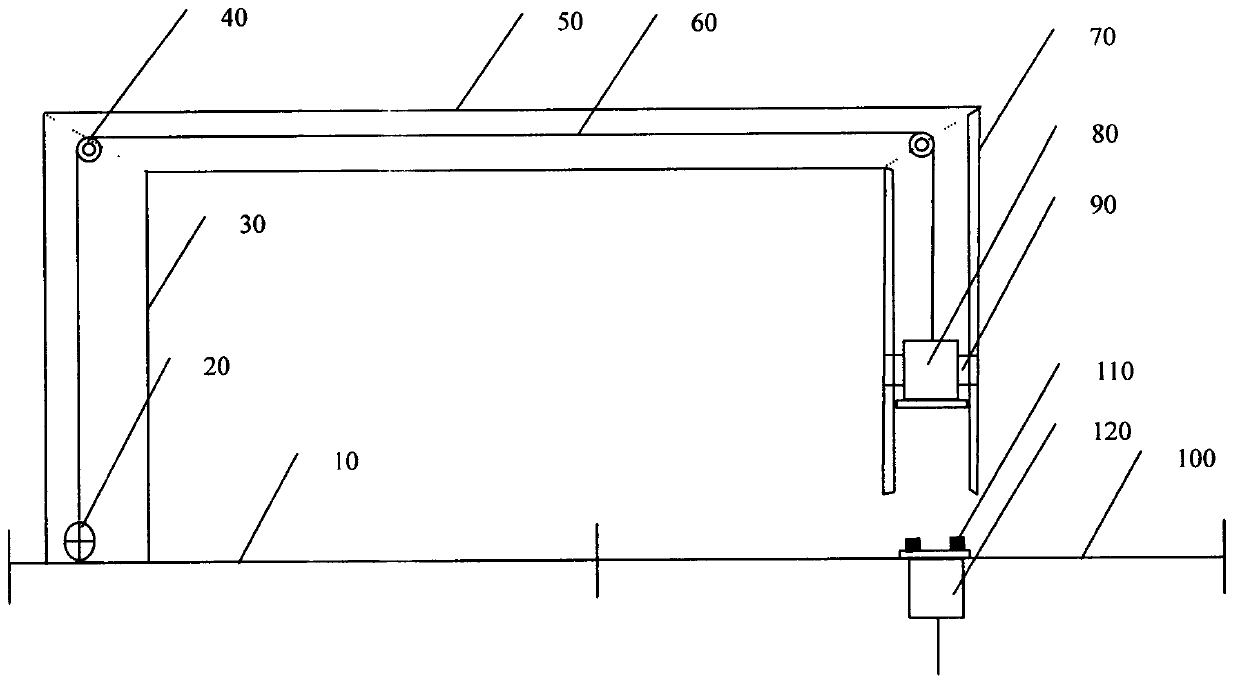
[0022] Such as figure 1 As shown, a detection system for upper and lower probes whose positions can be accurately calibrated is characterized by 10, support platform; 20, electric hoist; 30, round tube 1; 40, fixed pulley; 50, round tube 2; 60, steel wire rope 70, round tube 3; 80, upper probe; 90, upper probe limiter; 100, detection platform; 110, calibration ring block; 120, lower probe.

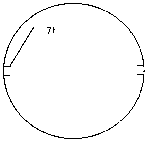
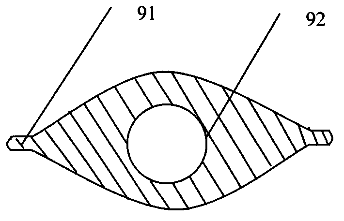
[0023] figure 2 It is a cross-sectional view of 70. Round tube 3, characterized by 71. Round tube card slot; image 3 It is a cross-sectional view of 90, the upper probe limiter, which is characterized by 91, PTFE, 92, rubber; Figure 5 It is a side view of 80, upper probe and 120, lower probe, characterized by 81, circular groove, 121, circular groove; Image 6 It is 100. The top view of the detection platform, which is characterized by 120, the lower probe, 101-104, the limit rod, 105, the pulley, 106, and the fixing clip.

[0024] Reference figure 1 , 2 , 3, 4, 5, 6, to complete the calibra...


PUM


Abstract

The invention discloses an upper probe and lower probe detection system with the position capable of being calibrated accurately and a calibration method of the upper probe and the lower probe detection system. The upper probe and lower probe detection system is characterized in that a lower probe can move on a detection platform optionally, an upper probe can ascend and descend, the upper probe accurately ascend and descend in the vertical direction in the process of ascending and descending, and round annular grooves are formed in contact surfaces of the upper probe and the lower probe. Through the connection structure of a steel wire rope and the upper probe, the gravity of the upper probe provides pressure for a detected sample, and therefore the use requirement can be met such as when the inner pressure of a vacuum insulated panel is detected. Due to the design of round tube clamping grooves and an upper probe limiter, the upper probe always moves in the vertical direction, and measurement is convenient. Due to the design of the circular annular clamping grooves and calibration blocks, a basis is provided for adjustment of the position of the lower probe, and accurate alignment of the upper probe and the lower probe can be guaranteed. Limiting rods of the detection platform are novel in design, flexible and simple, so that a foundation is laid for emergence of a plurality of sets of upper probes and lower probes. The calibration method is flexible, simple and suitable for multiple detection devices.

Description

Technical field [0001] The invention relates to a detection system for upper and lower probes whose positions can be accurately calibrated, in particular to a lower probe that can be moved arbitrarily on a detection platform, the upper probe can be raised and lowered, and the upper and lower probes are accurately aligned in the vertical direction during the lifting process. The contact surfaces of the upper and lower probes are provided with The position of the ring groove can be accurately calibrated up and down probe detection system. Background technique [0002] In many fields such as scientific research and product quality inspection, in order to achieve the purpose of detecting a certain performance, a set of vertical and accurately aligned probes are often required to cooperate with each other to achieve the purpose of detection. [0003] For example, CN202735023U (publication date is February 13, 2013) discloses a device for detecting the internal pressure of a vacuum insul...

Claims


Application Information

Patent Timeline
IPC IPC(8): G01L11/00G01L19/00G01L27/00
Inventor 陈照峰周万平
Owner TAICANG PAIOU TECH CONSULTING SERVICE
Learn More