A High Efficiency DC-DC Converter

A DC-DC and converter technology, applied in the field of high-efficiency DC-DC converters, can solve the problems of full-bridge current limitation, small size, and low current resistance requirements of devices, so as to reduce the loss of switching tubes and solve the current limitation , Reduce the effect of flow resistance requirements

Active Publication Date: 2016-09-21
湖南终南山科技发展有限公司
View PDF3 Cites 0 Cited by
  • Summary
  • Abstract
  • Description
  • Claims
  • Application Information

AI Technical Summary

Problems solved by technology

[0004] Aiming at the deficiencies of the prior art, the present invention proposes a switch tube that can realize zero-voltage turn-on and zero-current turn-on and turn-off at the same time, which can solve the current limitation problem of the traditional full bridge when making high power, and can realize small volume, High-efficiency DC-DC converters with low requirements for device current resistance

Method used


Image

  • A High Efficiency DC-DC Converter
  • A High Efficiency DC-DC Converter
  • A High Efficiency DC-DC Converter

Examples


Embodiment Construction

[0024] The present invention will be described below in conjunction with the accompanying drawings.

[0025] In order to make the object, technical solution and advantages of the present invention clearer, the present invention will be further described in detail below in conjunction with the accompanying drawings and embodiments. The specific embodiments described here are only used to explain the present invention, not to limit the present invention.

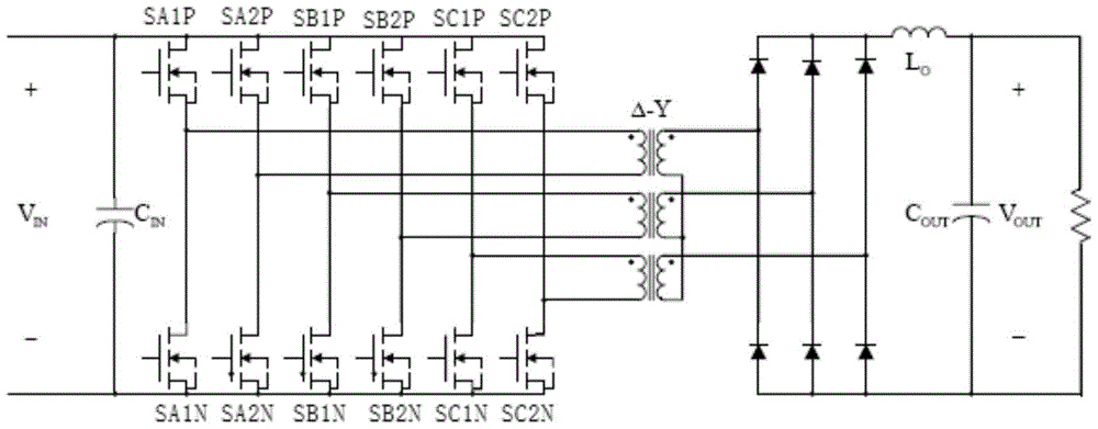
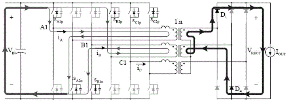
[0026] The input end of the DC-DC converter of the present invention includes three full bridges with the same structure, wherein each full bridge includes two bridge arms and a single-phase transformer, each bridge arm is formed by two switch tubes connected in series, all The bridge arms of the full bridge are connected in parallel with the input power supply; the input terminals of the transformer are respectively connected between the switching tubes of the bridge arms, and the output voltage is rectified by a rectifier ci...


PUM


Abstract

The invention relates to a high-efficiency DC-DC converter which comprises a first full bridge, a second full bridge and a third full bridge, wherein the first full bridge, the second full bridge and the third full bridge are identical in structure. Bridge arms of the full bridges are all connected with an input power supply in parallel, and the difference between the phase position of the first full bridge, the phase position of the second full bridge and the phase position of the third full bridge is 120 degrees. An on-bridge tube of the advancing bridge arm is driven first, and an under-bridge tube of the advancing bridge arm is driven half a period later than the on-bridge tube. An on-bridge tube of the lagging bridge arm is driven X periods of time later than the on-bridge tube of the advancing bridge arm. Due to the fact that in the five states for energy transmission at each order, at least one phase and at most two phases of the first full bridge, the second full bridge and the third full bridge work, in the whole process, currents are shared by the full bridges which work simultaneously, the current load of each full bridge is reduced, as a result, circuit loss is lowered effectively, the current limiting problem generated during power amplification through a traditional full bridge is solved, and the current resisting requirement of a device is also lowered. Due to the fact that the soft switching state is realized in a part of period, switching tube loss caused by the hard switching state of a switching tube is lowered, and the conversion efficiency of the DC-DC converter is improved.

Description

technical field [0001] The invention relates to a voltage converter, in particular to a high-efficiency DC-DC converter. Background technique [0002] In low-voltage, high-current power supply systems such as solar power generation systems and fuel cell power generation systems, DC-DC converters can convert fixed DC voltages into variable DC voltages and output them. It is a key executive component for changing, transmitting voltage, current and power control. The traditional DC-DC converter adopts the working mode of hard switching, and the factor affecting the working efficiency of the hard switching DC-DC converter is mainly the loss of the switching tube. The loss of the switching tube is mainly divided into two parts. One is the switching loss caused by the simultaneous existence of voltage and current during the turn-on and turn-off of the switch tube; Conduction loss due to the presence of resistance. [0003] The current DC-DC converter is mainly in the form of si...

Claims


Application Information

Patent Timeline
Patent Type & Authority Patents(China)
IPC IPC(8): H02M3/335
Inventor 王海龙常东来王宝珠
Owner 湖南终南山科技发展有限公司
Why Eureka
Try Eureka