IMS network message distribution method and device

A technology of network message and distribution device, applied in data exchange network, digital transmission system, electrical components, etc., can solve problems such as user call failure, IP address overlap, routing and forwarding errors, etc., to improve the success rate and improve IMS services. Quality, ensure the effect of normal routing

Active Publication Date: 2014-04-16
CHINA MOBILE GROUP JIANGSU
View PDF6 Cites 0 Cited by
  • Summary
  • Abstract
  • Description
  • Claims
  • Application Information

AI Technical Summary

Problems solved by technology

Since the SBC is connected to two bearer networks at the same time, the IP address of the CMNET on the access network side and the address of the dedicated IP bearer network on the IMS core network side need to be configured on the SBC at the same time. Interconnected with the CMNET / IP dedicated bearer network, the SBC acts as a back-to-back user agent (Back-to-BackUser Agent, B2BUA), used to end the signaling and media connection of the CMNET on the access network side, and the dedicated IP bearer on the core network side Assign new IP addresses and ports on the Internet to establish new signaling and media connections; at present, SBC uses simple and direct use of IP addresses for routing and forwarding, resulting in overlapping IP addresses on the access side or the network side. Routing and forwarding errors will directly cause the user's call to fail
[0005] Specifically, during the calling process of IMS users, some users failed to call or had one-way failures. Among them, when a city dialed an IMS number in the direction of another province, a one-way phenomenon occurred, after positioning, it was found that the signaling was normal. However, the media stream cannot be established normally. According to the normal call flow, inter-provincial IMS calls are carried by the IP dedicated bearer network. If the IP dedicated bearer network carries the IMS service, the planned IP address range is 10.184.76.0-10.184.99.0, but in the province The address segment in the CMNET network is planned to be used by the access-side NE terminal in another city, which will cause the route of the address segment on the SBC to point to CMNET instead of the IP-dedicated bearer network, so calls will occur. one-way phenomenon
The main reason for this failure is that the IP addresses used by the CMNET network on the access side and the IP-dedicated bearer network on the core network overlap, causing the SBC to send the route that should have been sent to the IP bearer network to the CMNET network with the same IP address.
[0006] In the IMS network environment, due to the overlap of IP addresses used by the CMNET network on the access side and the IP-dedicated bearer network on the core network side, user calls fail. By re-planning the IP address segment, the bearer network and the bearer network on the access network side can be avoided. The bearer network on the core network side uses the same IP address in the IMS service to avoid it. However, this method can only be solved after the problem is found, and because the IP address of CMNET can be allocated by each province, the IP dedicated bearer network address is in the carrier network. Therefore, in the IP address allocation process, it cannot be guaranteed that there will be no conflict between the IP address of the CMNET in the province and the IP address of the IP-dedicated bearer network in other provinces
[0007] Currently, IP address conflicts between the IP dedicated bearer network and CMNET are avoided by assigning IP addresses, which will not only limit the effective use of network IP addresses, but also modify the IP addresses used by users in the existing network. Data modification to related network elements, routers, user terminals and other equipment in the bearer network, the data modification amount and risk are large, and the IP address modification process will affect the normal communication of users, and the user perception is poor

Method used


Image

  • IMS network message distribution method and device
  • IMS network message distribution method and device
  • IMS network message distribution method and device

Examples


Embodiment Construction
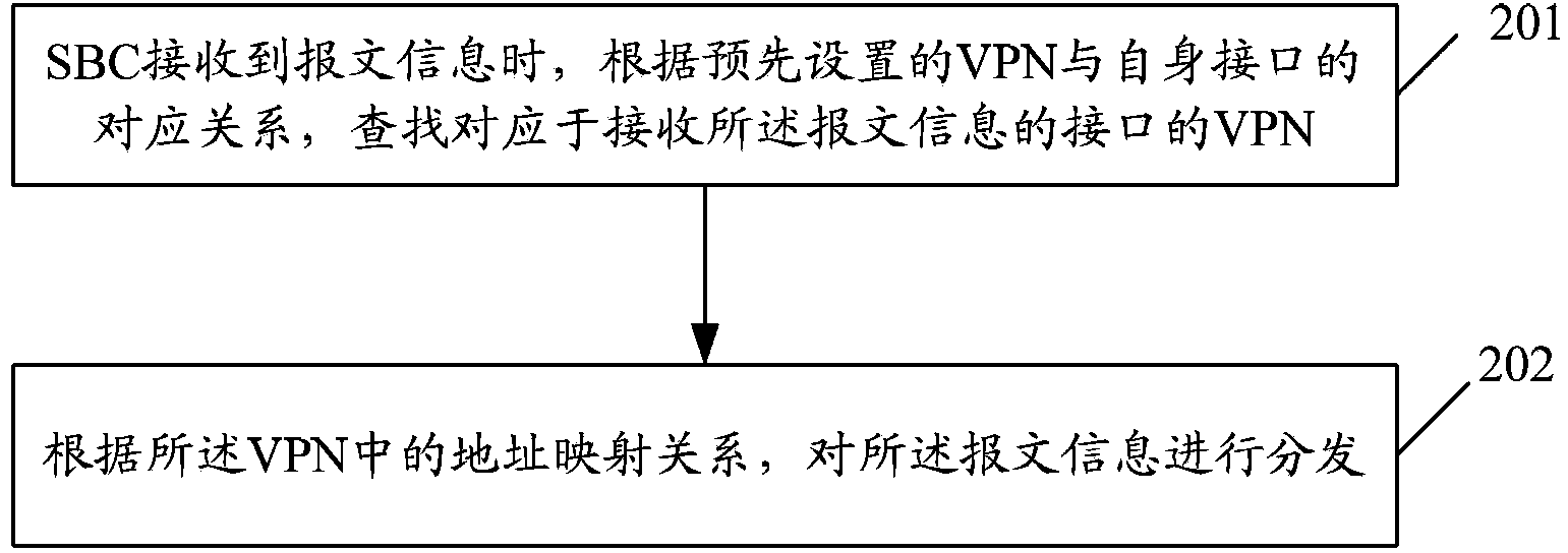
[0035] The basic idea of ​​the present invention is to isolate the physical interface / sub-interface of the SBC into different virtual local area networks (Virtual Private Network, VPN), and allow the same IP address in different VPNs. User; wherein, the sub-interface is a logical concept, and a physical interface may include multiple sub-interfaces.

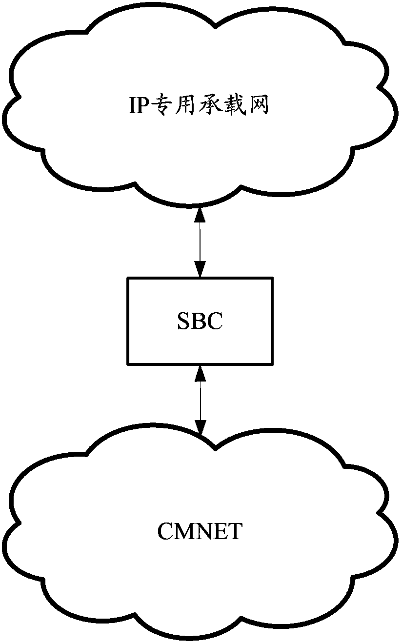
[0036] Here, each VPN has its own routing table and address resolution protocol (Address Resolution Protocol, ARP) entry. After receiving the message, the SBC will mark the corresponding VPN label for the interface according to the VPN to which the interface belongs. Routing and ARP addressing. By providing signaling and media traversal functions between specified VPNs, the SBC acts as a junction point for multiple networks to distribute terminal signaling, media, and management packets to corresponding networks.

[0037] Since the SBC can distinguish whether the received connection is a connection on the access side or a connec...


PUM


Abstract

The invention provides an IMS network message distribution method and device. The method includes the steps that when receiving message information, an SBC looks up VPNs corresponding to interfaces receiving the message information according to the corresponding relation between the preset VPNs and the interfaces of the VPNs; the message information is distributed according to an address mapping relation in the VPNs. The interfaces are isolated into different preset VPNs on the SBC, IP addresses are allowed to be the same in the different VPNs, and therefore the SBC can be connected to networks which are overlapped in link addresses through the different network interfaces, whether connection is access network side connection or core network side connection can be distinguished, even though IP addresses used in the access network side and the core network side may be overlapped, messages received on the access side can still not be forwarded to the access side again, and then normal routes of calling of users are guaranteed.

Description

technical field [0001] The invention relates to message distribution technology in core network services, in particular to an IP multimedia subsystem (IPMultimedia Subsystem, IMS) network message distribution method and device. Background technique [0002] The IMS network is the target architecture of the core network evolution. Its business and control separation architecture is conducive to the flexible and rapid provision of various business applications, and is more conducive to business integration; the IP-based bearer of the IMS network supports multiple fixed / mobile access methods. Convergence facilitates full-service operations. [0003] The networking of the existing IMS network is as follows: figure 1 As shown in the figure, the IP dedicated bearer network on the core network side and the CMNET on the access side are used to bear the bearer respectively; among them, the dedicated IP bearer network is responsible for communication between IMS core network elements...

Claims


Application Information

Patent Timeline
IPC IPC(8): H04L12/741H04L29/06H04L45/74
Inventor 解锦明于明曹基荣
Owner CHINA MOBILE GROUP JIANGSU
Why Eureka
Try Eureka