
welding equipment

A technology of welding equipment and high-frequency equipment, which is applied in welding equipment, mechanical equipment, metal processing equipment, etc., can solve the problems of high welding technology requirements, uneven distribution of magnetic lines of force, environmental pollution, etc., so as to avoid malfunction and improve Welding efficiency and welding cost reduction effects

Active Publication Date: 2016-06-29
GUANGDONG MEIZHI PRECISION MFG
View PDF8 Cites 0 Cited by
  • Summary
  • Abstract
  • Description
  • Claims
  • Application Information

AI Technical Summary

Problems solved by technology

However, flame brazing will produce strong light, a lot of heat and noise, which will affect the health of welding workers and cause some pollution to the environment.
Moreover, using the flame brazing process, a large number of pipes and valves need to be laid in the workshop. At the same time, the gas required for flame brazing is flammable and explosive, posing safety hazards
In addition, flame brazing requires high welding skills for welders and requires mature flame brazing technicians
[0003] In addition, there is another welding method using U-shaped electromagnetic coils, but when using U-shaped electromagnetic coils for welding, due to the uneven distribution of magnetic force lines, there is no magnetic force lines at the U-shaped opening, and the heat can only be slowly transferred to the opening of the U-shaped coil. Long heating time and low efficiency
However, O-shaped coils used in other fields cannot be welded due to interference with components such as the compressor liquid reservoir.

Method used


Image

  • welding equipment
  • welding equipment
  • welding equipment

Examples


Embodiment Construction

[0038] Embodiments of the present invention are described in detail below, examples of which are shown in the drawings, wherein the same or similar reference numerals designate the same or similar elements or elements having the same or similar functions throughout. The embodiments described below by referring to the figures are exemplary and are intended to explain the present invention and should not be construed as limiting the present invention.

[0039] In describing the present invention, it should be understood that the terms "center", "longitudinal", "transverse", "length", "width", "thickness", "upper", "lower", "front", " Orientation or position indicated by "back", "left", "right", "vertical", "horizontal", "top", "bottom", "inner", "outer", "clockwise", "counterclockwise", etc. The relationship is based on the orientation or positional relationship shown in the drawings, and is only for the convenience of describing the present invention and simplifying the descrip...


PUM


Abstract

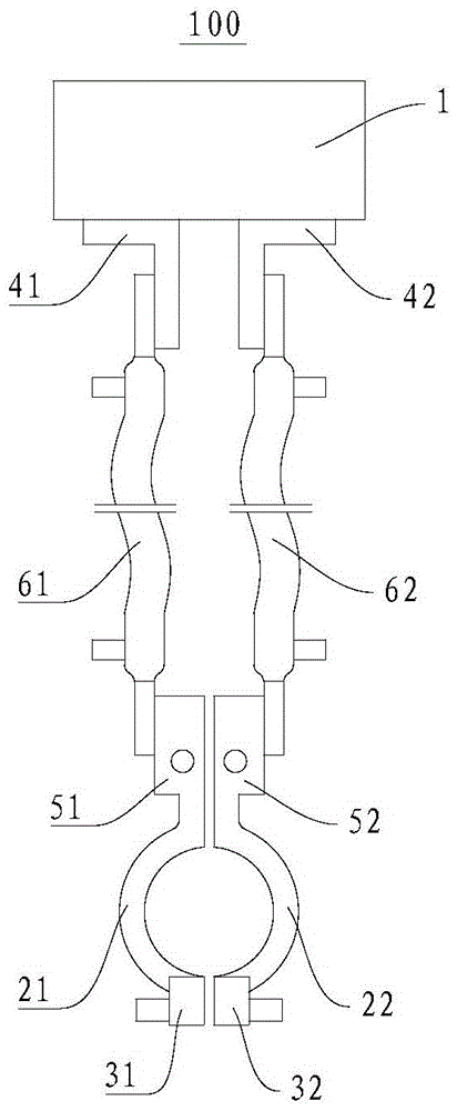
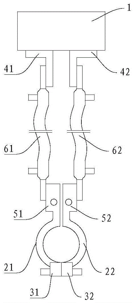
The invention discloses a welding device. The welding device comprises a high frequency device, a first coil section, a first flexible conductor, a second coil section and a second flexible conductor, wherein two ends of the first flexible conductor are respectively connected with the high frequency device and a first end of the first coil section, two ends of the second flexible conductor are respectively connected with the high frequency device and a first end of the second coil section, and the relative positions of the first coil section and the second coil section are adjustable so that the first coil section and the second coil section can be switched between a matched state and a separated state. When the first coil section and the second coil section are in the matched state, the first end of the first coil section is adjacent to the first end of the second coil section, and a second end of the first coil section is in contact with a second end of the second coil section; and when the first coil section and the second coil section are in the separated state, the second end of the first coil section is separated from the second end of the second coil section. The welding device can be used for welding a welding air suction pipe, a cylinder connecting pipe and a liquid storage device bend and is short in welding time and high in efficiency.

Description

technical field [0001] The invention relates to a welding device. Background technique [0002] The suction pipe of the compressor, the connecting pipe of the cylinder and the elbow pipe of the liquid receiver are generally fixed by welding. At present, the flame brazing process is mostly used in the industry. However, flame brazing will produce strong light, a lot of heat and noise, which will affect the health of welders and cause some pollution to the environment. Moreover, the flame brazing process requires the laying of a large number of pipes and valves in the workshop, and the gas required for flame brazing is flammable and explosive, posing potential safety hazards. In addition, flame brazing requires high welding skills for welders and requires mature flame brazing technicians. [0003] In addition, there is another welding method using U-shaped electromagnetic coils, but when using U-shaped electromagnetic coils for welding, due to the uneven distribution of magn...

Claims


Application Information

Patent Timeline
Patent Type & Authority Patents(China)
IPC IPC(8): B23K1/002B23K3/08
CPCB23K3/0475B23K3/085B23K2101/10
Inventor 李林虞阳波杨泾涛
Owner GUANGDONG MEIZHI PRECISION MFG
Learn More