
Sealing device with compensation facility for multiple directions of movement

A technology of sealing equipment and equipment, which is applied in the direction of engine sealing, mechanical equipment, engine components, etc., and can solve the problem of not having the ability to rotate

Active Publication Date: 2014-04-23
KRONES AG
View PDF5 Cites 1 Cited by
  • Summary
  • Abstract
  • Description
  • Claims
  • Application Information

AI Technical Summary

Problems solved by technology

Traditional bellows-like devices of this type do not have the ability to rotate

Method used


Image

  • Sealing device with compensation facility for multiple directions of movement
  • Sealing device with compensation facility for multiple directions of movement
  • Sealing device with compensation facility for multiple directions of movement

Examples


Embodiment Construction

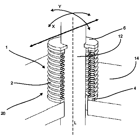
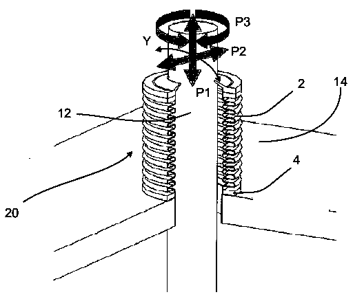
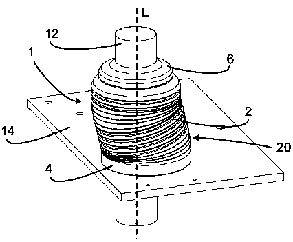
[0067] figure 1 It is a structural schematic diagram of the sealing device 1 . In the embodiment, a wall body 14 or a wall body unit 14 is included, and a motion unit 12 that moves relative to the wall body 14 is included. In this case, the middle part between the wall body and the motion unit 12 can be formed by The sealing device 1 is sealed. In this way, it is possible, for example, to create a sterile room below said wall 14 , providing a (non-sterile) environment for the space above the wall 14 . Preferably, the cavity 14 has an opening 15 with a cross section larger than that of the moving unit 12 (such as figure 2 shown), guide the motion unit to move through the opening 15 .

[0068] The sealing device 1 comprises a first end 4 fixed to the wall 14 . The second end 6 of the sealing device rests against the strip-shaped portion of the movement unit 12 . The reference letter X designates one possible direction of movement of the movement unit 12 . In an embodiment...


PUM


Abstract

The device has a seal device (1) comprising a main body (2), which is formed from a resilient and gas-tight material and extends in a peripheral direction. An end portion (4) is fastened to a wall element (14). Another end portion (6) is set against a moving element (12) and movable with respect to the former end portion in a transverse direction (X), which extends at an angle different from 0 degree with respect to a longitudinal direction (L). A sliding seal unit (20) is applied to the moving element such that a relative rotation is made possible between the elements by a pre-set angle.

Description

technical field [0001] The present invention relates generally to the beverage production industry and the packaging industry. At the same time, it relates to various equipment and methods known from the prior art for processing containers, for example, filling equipment, sealing equipment, transportation equipment, sterilization equipment and other related equipment. Background technique [0002] The filling process of some beverages needs to be carried out in a sterile room. In this case, the containers need to be transported to a sterile room and processed, eg filled, sealed or sterilized in the sterile room. During this process, the sterile room should be isolated from the external environment to ensure a reliable sterilization process. [0003] Many of the above-mentioned processing devices comprise a processing unit which performs operations in a sterile room, for example, including the capping process of screwing the caps on the containers. In addition, a driving d...

Claims


Application Information

Patent Timeline
Patent Type & Authority Applications(China)
IPC IPC(8): B65B55/04F16J15/52
CPCF16J15/44B29C49/46A61L2/00B29C2049/4697
Inventor 佛罗瑞恩·格尔廷格迈克尔·纽鲍尔
Owner KRONES AG
Learn More