
Sealing parts

A technology for sealing parts and components, applied in the field of gap rings, which can solve the problems of low operational reliability

Active Publication Date: 2017-10-24
KSB AG
View PDF2 Cites 0 Cited by
  • Summary
  • Abstract
  • Description
  • Claims
  • Application Information

AI Technical Summary

Problems solved by technology

Here, due to the fact that the flow efficiency of the throttling slot is in an inverse relationship with wear and operational reliability, the higher the efficiency, the higher the wear and the lower the operational reliability

Method used


Image

  • Sealing parts
  • Sealing parts

Examples


Embodiment Construction

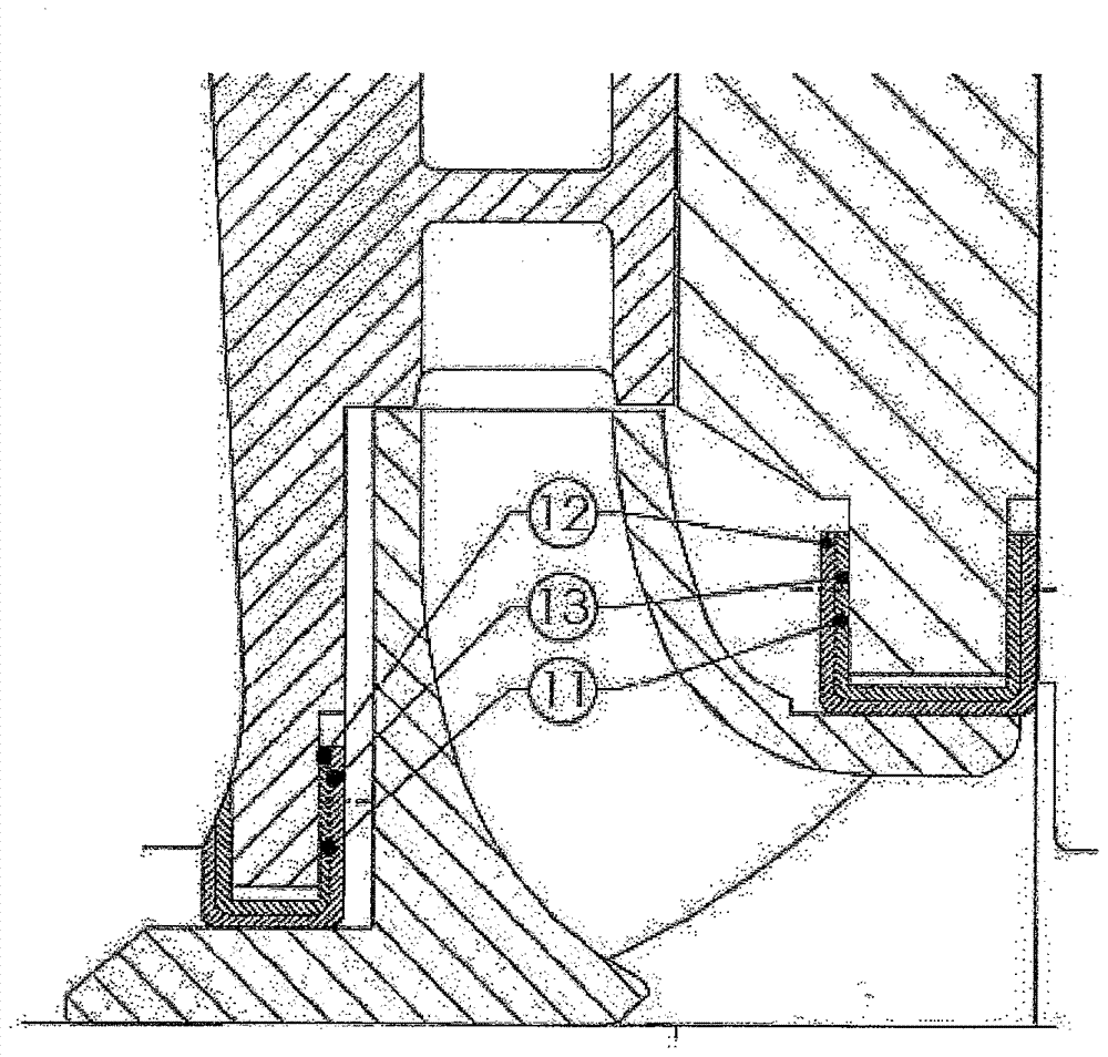
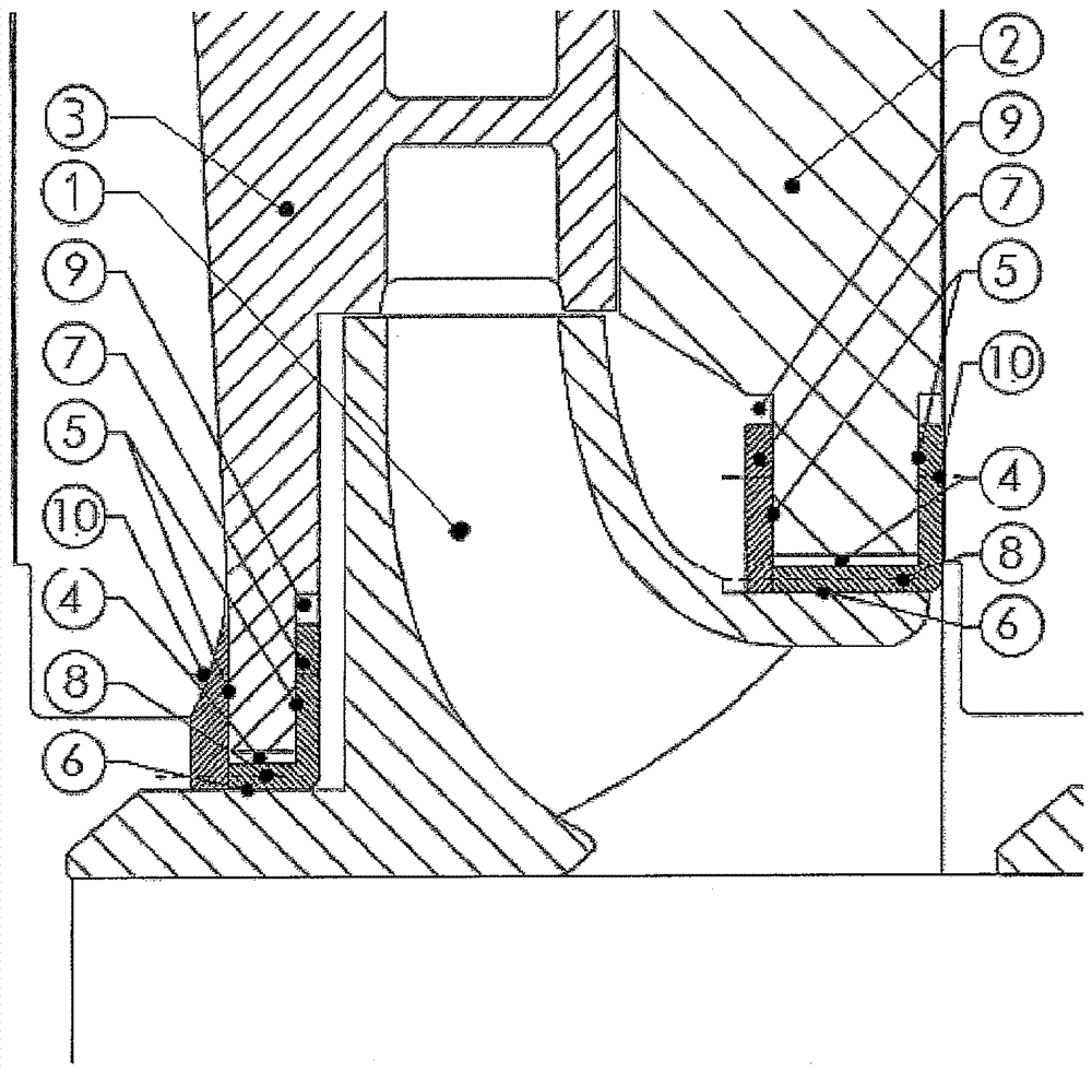
[0020] in figure 1 The first embodiment of the gap ring sealing structure according to the present invention is shown in detail in the example, in which an impeller pump is used in the example. The impeller pump impeller 1 is shown, which in this structure is a rotating rotor part, where it rotates relative to the housing 2 and the guide wheel 3, which are regarded as stators in a fixed position.

[0021] According to the invention, the gap is surrounded by a U-shaped one-piece or multi-piece cylindrical gap ring 7. The slit ring is arranged in the stator composed of the housing 2 and the guide wheel 3 by the slit diameter of the impeller or the impeller pump impeller 1, wherein the slit ring is matched with the U-shaped anti-twist 10 or the inner layer 12 and the outer layer 13 for guidance. Inside the shell.

[0022] The gap ring 7 realizes two radial functional gaps. The gap diameter of the existing radial throttling or impeller pump impeller is used as the gap that always flow...


PUM


Abstract

A sealing element for sealing a rotating component (1) relative to a stationary housing (2) as a gap ring with a self-adjusting throttle gap (6), wherein between the rotating component and the housing A slot ring ( 7 ) is provided in the slot, wherein a medium-filled annular chamber ( 4 ) is formed on the surface of the radially limiting slot on the stationary housing, wherein the annular chamber is aligned in such a way that it is The rotating parts are concentric, wherein the annular chamber is surrounded by a u-shaped slot ring (7), wherein an axial throttle slot is provided between the u-shaped slot ring (7) and the housing (2), and in the slot Between the ring (7) and the rotating component (1) there is a radial slot filled with medium and flowing through.

Description

Technical field [0001] The present invention relates to a slit ring of a fluid throttling slot of a fluid machine for conveying a liquid, especially a throttling slot on an impeller of an impeller pump. Background technique [0002] In various embodiments, a throttle slit composed of a slit ring, for example for a vane pump, is known. They seal the gap between rotating rotor parts, such as the impeller of an impeller pump, and a stationary stator, such as a housing. Since there is a minimum gap width for the necessary errors when processing various parts, it just prevents the parts from contacting and resulting friction and wear. In order to reduce the loss on the above-mentioned gap, there are different gap sealing embodiments, but they are subject to more or less severe wear according to the form of conveying medium. A distinction is made between axial and radial throttle slit structures. In the axially movable structural components, the corresponding axial sealing seam can ...

Claims


Application Information

Patent Timeline
Patent Type & Authority Patents(China)
IPC IPC(8): F04D29/16
CPCF04D29/167F16J15/164F04D29/16
Inventor J.H.伦克
Owner KSB AG
Learn More