Buckling restrained brace with staggered intersecting plates

A buckling restraint and cross-slab technology, applied in building components, earthquake-proof and other directions, can solve the problems of reducing the buckling restraint support performance, single variety of isolation materials, difficult concrete construction, etc., to simplify the processing difficulty, reduce the cost, and avoid conflicts.

Active Publication Date: 2014-04-23
SOUTHEAST UNIV
View PDF8 Cites 8 Cited by
  • Summary
  • Abstract
  • Description
  • Claims
  • Application Information

AI Technical Summary

Problems solved by technology

[0006] The present invention solves the requirement of manufacturing accuracy and high manufacturing cost of the buckling restraint support of the outer constrained section of reinforced concrete or the combined outer constrained section of steel and concrete, the difficulty of wet construction such as concrete, the single type of isolation material coated on the surface of the inner core member, and poor durability. , and energy-dissipating inner core members need to be cut or chamfered, which will bring additional processing and reduce the performance of buckling-constrained supports. A buckling-constrained support for dislocated cross plates

Method used


Image

  • Buckling restrained brace with staggered intersecting plates
  • Buckling restrained brace with staggered intersecting plates
  • Buckling restrained brace with staggered intersecting plates

Examples


Embodiment 1

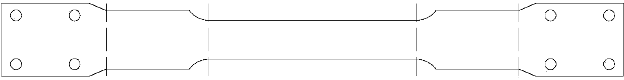
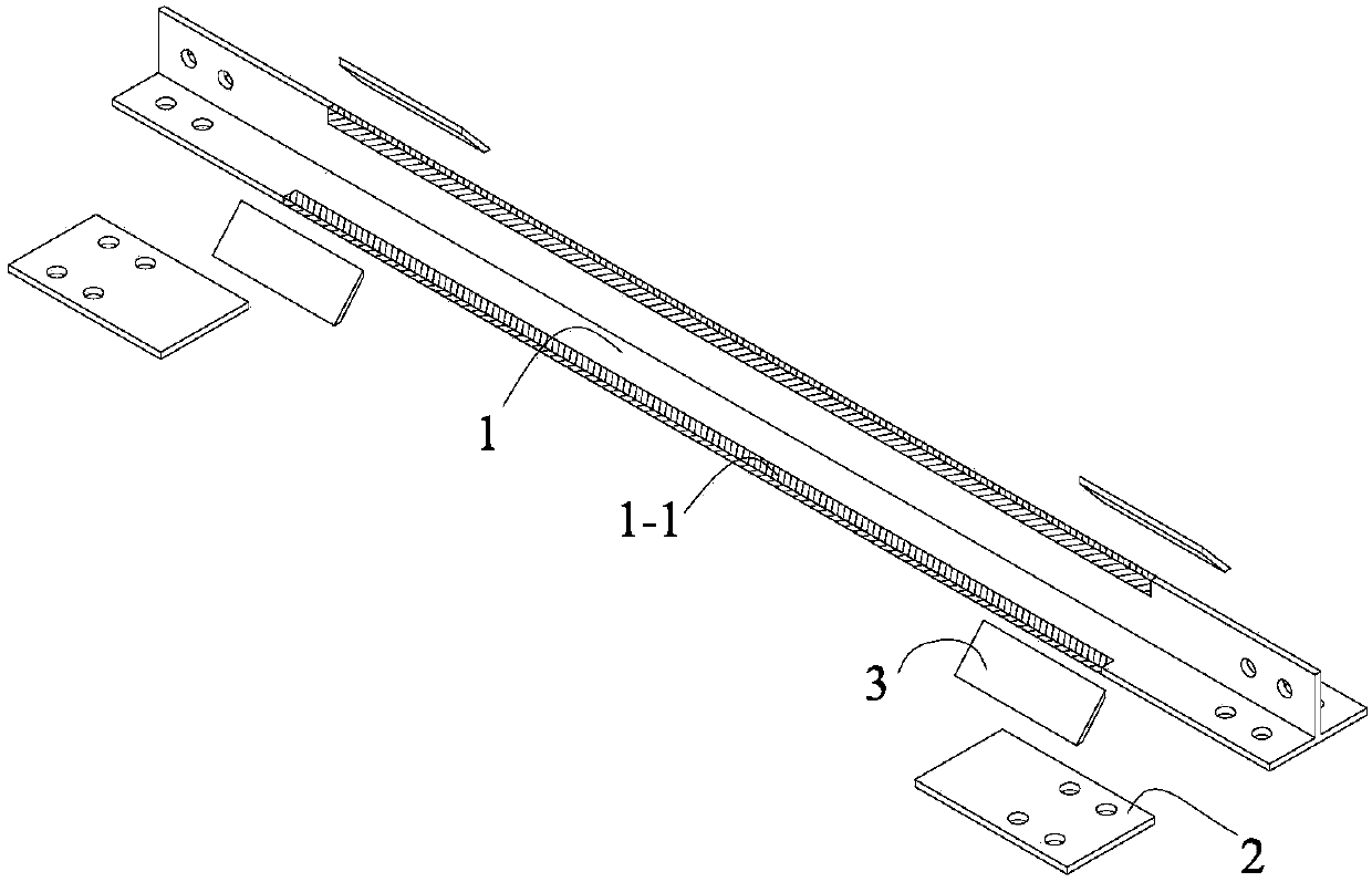
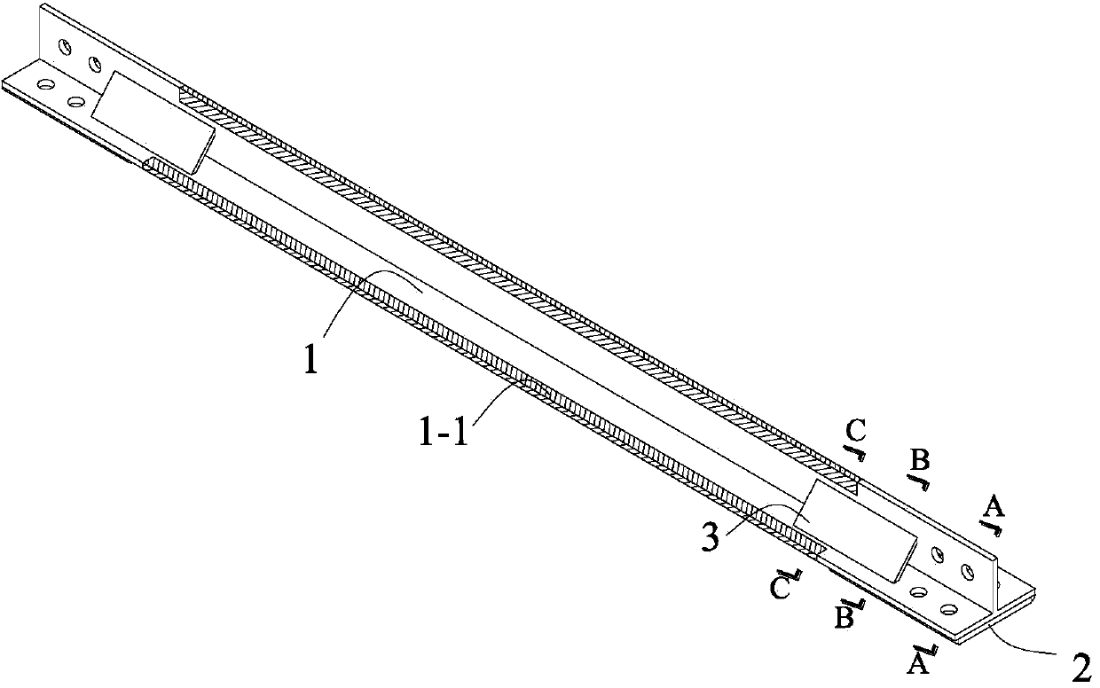
[0047] Such as Figure 2-10 Shown: a buckling-constrained brace of a misplaced cross plate, including an energy-dissipating inner core member 1, a first group of reinforcement plates 2, a second group of reinforcement plates 3, and a buckling restraint component 4 of equal cross-section; the first group of reinforcement plates 2 is welded At the two ends of the energy dissipation core member 1, the second set of reinforcement plates 3 are welded to the flange or web of the energy dissipation inner core member 1 near the root 1 / 2, and the solid along the length direction of the energy dissipation core member 1 The connection point is located inside the first group of reinforcement plates 2, and the end point is located inside the constant-section buckling restraint component 4, and the first group of reinforcement plates 2 and the second group of reinforcement plates 3 are welded to different positions of the cross-section of the energy-dissipating inner core member 1, Partial in...

Embodiment 2

[0049] Such as Figures 11-16 As shown: this embodiment is the same as the rest of embodiment 1, the difference is that the energy-dissipating inner core board 1 is an I-shaped section, and the specific fixed position of the second group of reinforcement boards 3 is changed.

Embodiment 3

[0051] Such as Figure 17 Shown: this embodiment is the same as the rest of embodiment 1, the difference is that the second set of reinforcing plates 3 is angle steel.


PUM


Abstract

The invention discloses a buckling restrained brace with staggered intersecting plates. The buckling restrained brace comprises a dissipating core component, a first reinforcing plate group, a second reinforcing plate group, and a uniform-section buckling restraint part. The first reinforcing plate group is fixedly connected to outer surfaces of two flanges of two tail ends of the dissipating core component. The uniform-section buckling restraint part is disposed outside the middle of the dissipating core component. The second reinforcing plate group is fixedly connected between the flanges and webs of the dissipating core component. The buckling restrained brace with staggered intersecting plates has the advantages that the middle of the dissipating core component can yield first and the ends of the dissipating core component can be in the elastic phase under the action of high external force, with no need of cutting a dissipating core plate, and accordingly damage of the dissipating core component caused by cutting is avoided; only the flanges or web edges of the dissipating core component are restrained, overall and local buckling of the dissipating core component is effectively guaranteed, conflict between the buckling restraint part and the two reinforcing plate groups is avoided, the section of the buckling restraint part in the length-wise direction is equal, and manufacturing difficulty is significantly reduced.

Description

technical field [0001] The invention belongs to the field of civil engineering and relates to a buckling constraint support for reducing the seismic response of engineering structures. Background technique [0002] Before the 1990s, the traditional anti-seismic method used to dissipate the seismic energy through the local yield of the main structure, such as the beam-hinge mechanism. Facilitate the post-earthquake repair of structures. Since the Hanshin Earthquake in Japan and the Northridge Earthquake in the United States, buckling-restrained braces, as an energy-dissipating and shock-absorbing member with superior performance, have been rapidly popularized and applied in Japan, the United States and other earthquake-prone developed countries, and their research in my country is also developing. stage. The buckling-constrained support wraps the constrained components outside the core components to limit the bending deformation of the core components. The seismic energy is ...

Claims


Application Information

Patent Timeline
Patent Type & Authority Applications(China)
IPC IPC(8): E04B1/98
Inventor 王春林孟少平曾滨葛汉彬曾鹏
Owner SOUTHEAST UNIV
Why Eureka
Try Eureka