Expansion pipe completing tool

A technology of expanding pipes and tools, which is applied in wellbore/well parts, earthwork drilling, sealing/isolation, etc. It can solve problems such as inability to achieve variable diameter expansion, unsmooth running, and limited expansion cone size, etc., to achieve Ensure the reliability of the expansion process, reduce the risk of running into obstacles, and ensure the effect of construction reliability

Inactive Publication Date: 2014-04-23
PETROCHINA CO LTD
View PDF7 Cites 5 Cited by
  • Summary
  • Abstract
  • Description
  • Claims
  • Application Information

AI Technical Summary

Problems solved by technology

[0003] At present, in the field application of expansion tube technology, there is a contradiction between the difficulty of loading and the expected large expansion volume, that is, the large expansion rate leads to the excessive expansion cone size. The expansion cone of the conventional expansion tube tool used in China is built-in, that is, the expansion The cone is placed in the expansion tube body before the expansion tube is expanded, which makes the expansion tube body must have a wide-diameter firing cavity that can accommodate the expansion cone. The existence of the wide-diameter firing cavity makes the expansion tube in the process of running It is easy to encounter the risk of being blocked, resulting in unsmooth running or failure; in addition, most of the expansion cones currently used in China are integral structures, which cannot achieve variable diameter expansion. In order to ensure the safety of running and expansion, the expansion cone The size is severely limited, and it is mostly compensated by increasing the thickness of the rubber sealing ring outside the expansion pipe, resulting in a large loss in the inner diameter of the wellbore after expansion

Method used


Image

  • Expansion pipe completing tool

Examples


Embodiment Construction

[0031] The following will clearly and completely describe the technical solutions in the embodiments of the present invention with reference to the accompanying drawings in the embodiments of the present invention. Obviously, the described embodiments are only some, not all, embodiments of the present invention. Based on the embodiments of the present invention, all other embodiments obtained by persons of ordinary skill in the art without creative efforts fall within the protection scope of the present invention.

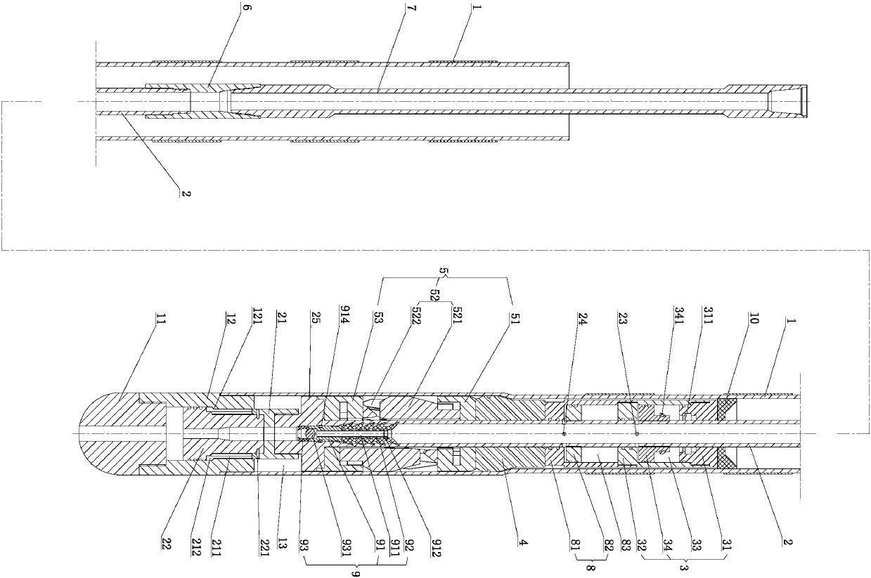
[0032] Such as figure 1 As shown, the present invention provides an expansion tube completion tool, which includes an expansion tube 1, a center pipe 2, a primary hydraulic cylinder 3 and a primary expansion cone 4, wherein: the lower end of the expansion tube 1 is connected with a floating shoe 11; The tube 2 is set in the expansion tube 1, and the lower end of the central tube 2 is connected with an expanding cone locking split claw 21 and an expanding cone locki...


PUM


Abstract

The invention provides an expansion pipe completing tool. The expansion pipe completing tool comprises an expansion pipe, a central pipe, a first level hydraulic cylinder and a first level expansion cone; the lower end of the expansion pipe is connected with a float shoe; the central pipe is arranged inside the expansion pipe in a penetration mode; the lower end of the central pipe is sequentially connected with an expansion cone locking splitting claw and an expansion cone locking mandrill; the upper end of the central pipe is provided with a first penetration hole; the first level hydraulic cylinder is sleeved to the central pipe position which is provided with the first penetration hole; the first level expansion cone which is sleeved to the central pipe is arranged at the lower end of the first level hydraulic cylinder; the lower end of the first level expansion cone is provided with a reducing expansion cone which is sleeved to the central pipe. According to the expansion pipe completing tool, the reducing expansion cone which is in a combined type reducing structure enables the diameter of a pipe column to be minimum and lowering resistance risks to be reduced when the pipe column lowers to an open hole well, the reducing cone can provide a large expansion rate after being assembled, and the well hole size is not loosed or loosed as little as possible during expansion pipe completing.

Description

technical field [0001] The present invention relates to an expansion tube completion tool, in particular to an expansion tube completion tool used in the petroleum industry. Background technique [0002] Expandable pipe technology is a new technology that has been booming in recent years, and it can be applied to drilling, well completion, oil production, workover and other operations. The expansion process of the expansion tube is the process of cold hardening of the tube body, and the expansion methods include mechanical and hydraulic. [0003] At present, in the field application of expansion tube technology, there is a contradiction between the difficulty of loading and the expected large expansion volume, that is, the large expansion rate leads to the excessive expansion cone size. The expansion cone of the conventional expansion tube tool used in China is built-in, that is, the expansion The cone is placed in the expansion tube body before the expansion tube is expand...

Claims


Application Information

Patent Timeline
Patent Type & Authority Applications(China)
IPC IPC(8): E21B29/00E21B23/01E21B33/10
Inventor 孙强李涛李益良韩伟业陈强明尔扬毕秀玲薛建军丁爱芹
Owner PETROCHINA CO LTD
Why Eureka
Try Eureka