Backlight module and display device

A backlight module and high-beam technology, applied in light guides, optics, optical components, etc., can solve problems such as reducing the utilization rate of light energy, achieve the effects of improving light leakage, reducing loss of light energy, and improving utilization rate

Inactive Publication Date: 2014-04-23
BEIJING BOE OPTOELECTRONCIS TECH CO LTD +1
View PDF5 Cites 7 Cited by
  • Summary
  • Abstract
  • Description
  • Claims
  • Application Information

AI Technical Summary

Problems solved by technology

[0003] see figure 1 , the light guide plate 3' is arranged under the optical film material 2', the light guide plate 3' includes a light incident surface 32' and a far light surface 31' opposite to the light incident surface, and the plastic frame is arranged on the periphery of the light guide plate 3', wherein , the plastic frame edge located on the high beam surface 31' side of the light guide plate 3' is the first frame edge 11', and the plastic frame edge located on the light incident surface 32' side of the light guide plate 3' is the second frame edge 12' The far beam surface 31' of the light guide plate 3' is opposite to the first surface 111' of the first frame side 11', and the light of the light-emitting element enters the light guide plate 3' from the light incident surface of the light guide plate 3', wherein a part of the light For total reflection, it propagates toward the direction of the high beam surface and emits from the high beam surface 31' of the light guide plate 3', thereby forming a bright line on the side of the high beam surface 31', thereby causing defects such as bright bands in the display device. The traditional The solution is to use light-shielding tape for shading, so as to avoid the generation of bright bands. However, because the light-shielding tape is black, it can absorb the light that hits the tape, thereby reducing the utilization of light energy.

Method used


Image

  • Backlight module and display device
  • Backlight module and display device
  • Backlight module and display device

Examples


Embodiment 1

[0026] This embodiment provides a backlight module, including a light guide plate and a plastic frame located around the light guide plate, the light guide plate includes a light incident surface and a high beam surface opposite to the light incident surface, the plastic frame It includes a first frame opposite to the far light surface of the light guide plate, the first frame includes a first surface opposite to the far light surface of the light guide plate, wherein the first surface has a first microstructure, The first microstructure is used to reflect light incident on the first microstructure to various directions.

[0027] In this embodiment, by setting a first microstructure on the first surface of the first frame of the plastic frame, the first microstructure can scatter the relatively concentrated light incident on the surface, so that the light can be reflected in different directions, Therefore, bright lines will not be formed on the far light side of the light gui...

Embodiment 2

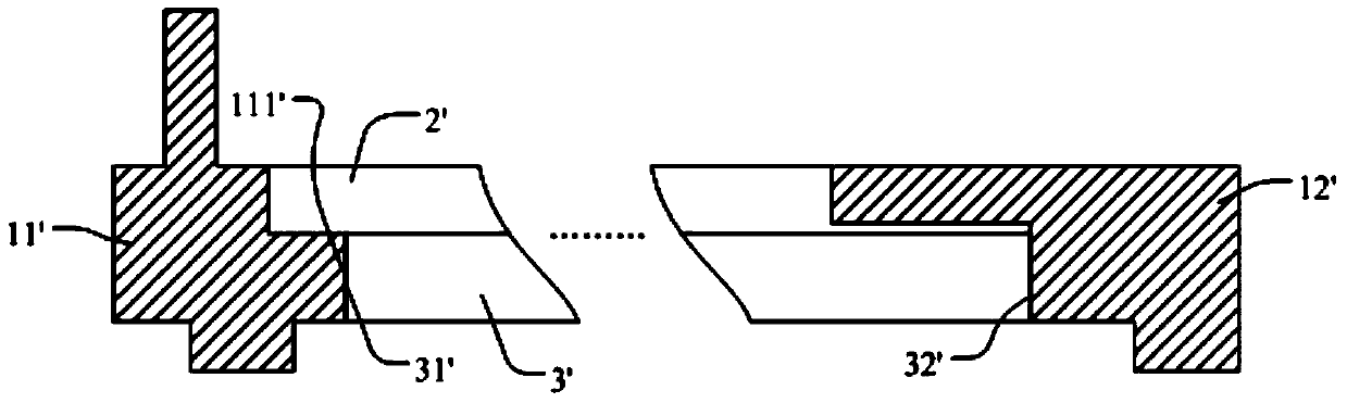
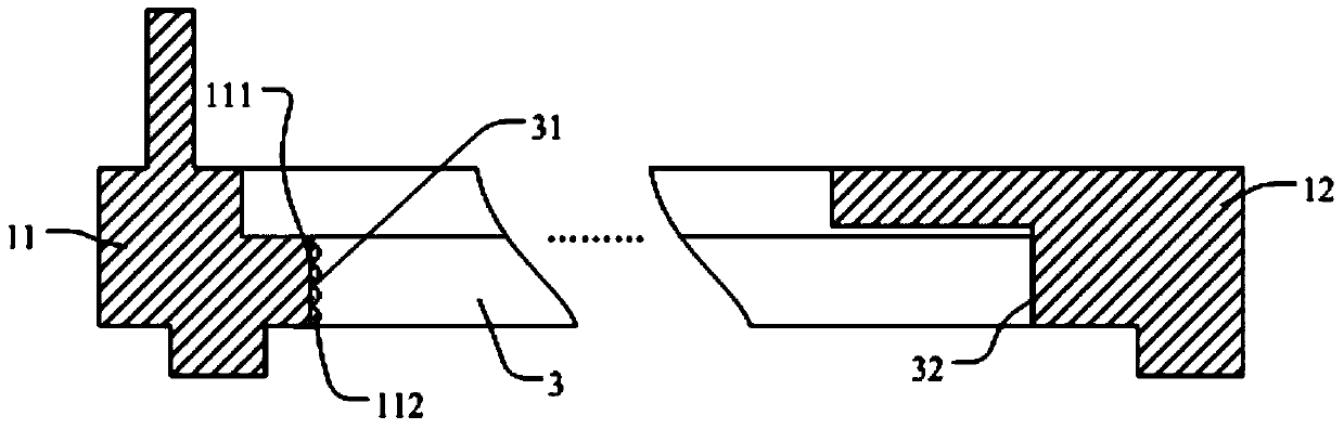
[0029] figure 2 It is a schematic diagram of a backlight module provided in this embodiment. The backlight module includes a light guide plate 3 and a plastic frame located around the light guide plate. The light guide plate 3 includes a light incident surface 32 and a far side opposite to the light incident surface 32 Optical surface 31, the plastic frame includes a first frame 11 opposite to the high beam surface 31 and a second frame 12 opposite to the light incident surface 32, wherein the first frame 11 includes a frame opposite to the high beam surface 31 of the light guide plate The first surface 111 , wherein the first surface 111 has a first microstructure, and the first microstructure is used to reflect light incident on the first microstructure to various directions. Specifically, when the light in the light guide plate is incident on the first surface from the high beam surface 31, it will be chaotically reflected in various directions by the first microstructures...

Embodiment 3

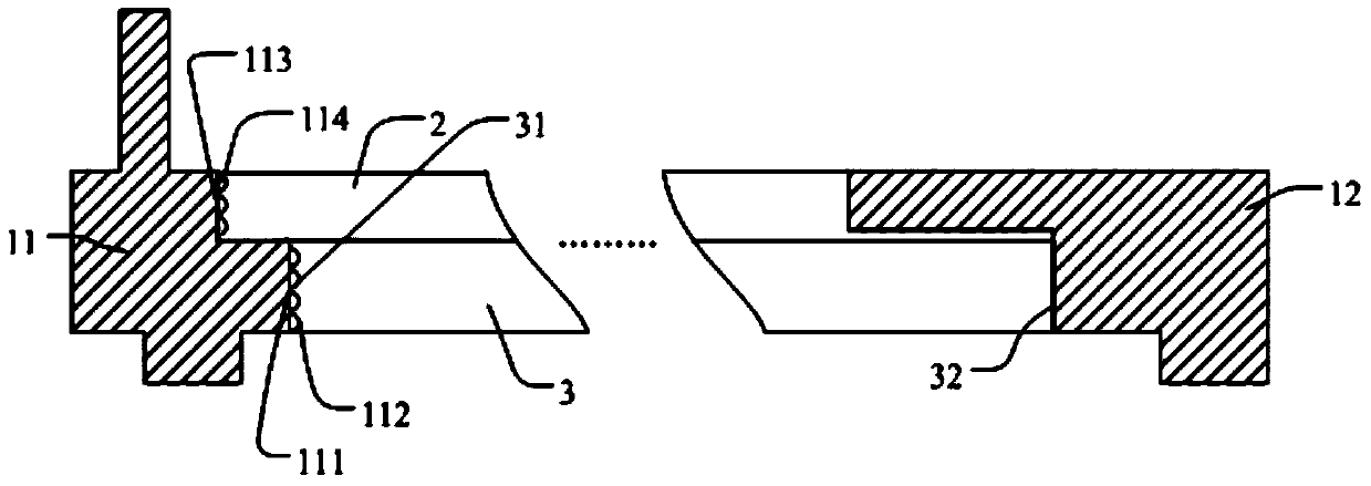
[0032] see image 3 , image 3 It is a schematic diagram of a backlight module provided in this embodiment. The backlight module includes a light guide plate 3 and a plastic frame located around the light guide plate. The light guide plate 3 includes a light incident surface 32 and a far side opposite to the light incident surface 32 Optical surface 31, the plastic frame includes a first frame 11 opposite to the high beam surface 31 and a second frame 12 opposite to the light incident surface 32, wherein the first frame 11 includes a frame opposite to the high beam surface 31 of the light guide plate The first surface 111, the first surface 111 has a first microstructure, and the first microstructure is used to reflect the light incident on the first microstructure to various directions, and the backlight module also includes a The optical film material 2 above the light guide plate, wherein the first frame 11 also includes a second surface 113 opposite to the optical film ma...


PUM

PropertyMeasurementUnit
Diameteraaaaaaaaaa
Diameteraaaaaaaaaa

Abstract

The invention provides a backlight module and a display device. The backlight module comprises a light guide plate and a plastic frame around the light guide plate. The light guide plate comprises an incident face and a light-emitting face opposite to the incident face. The plastic frame comprises a first frame opposite to the light guide plate. The first frame comprises a first surface which is opposite to the light-emitting face of the light guide plate and which is provided with a first microstructure. The first microstructure of the first surface of the first frame of the plastic frame can scatter relatively-condensed light emitted to the first surface, so that the light can be reflected in different directions, bright light never forms on the light-emitting side of the light guide plate and light leakage is improved; meanwhile, the first microstructure reflects all or part of the incoming light into the light guide plate, the light cannot be directly reflected out of a backlight source, and light energy utilization rate is increased accordingly.

Description

technical field [0001] The invention relates to the display field, in particular to a backlight module and a display device. Background technique [0002] Liquid crystal displays have the advantages of small size, low power consumption, and low radiation, and have been widely used in equipment such as computer monitors, notebook computers, mobile phones, and LCD TVs. Since the display panel of the liquid crystal display does not emit light, in order to achieve the display effect, the backlight module needs to provide light source for it. At present, the main components of the backlight module include light-emitting elements, reflectors, light guide plates, optical films Frame and backplane, etc. Among them, the main function of the light guide plate is to guide the light beam emitted by the light-emitting element upward evenly, and its structure and material play a great role in the final brightness and uniformity of the backlight module; To connect or locate other componen...

Claims


Application Information

Patent Timeline
IPC IPC(8): G02F1/1333G02F1/13357
CPCG02B6/0088G02B6/005G02F1/133317G02B6/0031
Inventor 安喜君权宁万杨刚
Owner BEIJING BOE OPTOELECTRONCIS TECH CO LTD
Why Eureka
Try Eureka