Modularization double-swing solar energy automatic tracking apparatus
An automatic tracking device and double-swing technology, applied in the field of solar energy utilization, can solve the problems of easy wear of the pointed push rod, need to improve the accuracy retention, cumbersome reverse solution of the parallel mechanism, etc., and achieve high tracking accuracy and repeated tracking positioning accuracy good effect
- Summary
- Abstract
- Description
- Claims
- Application Information
AI Technical Summary
Problems solved by technology
Method used
Image

Examples
Embodiment 1
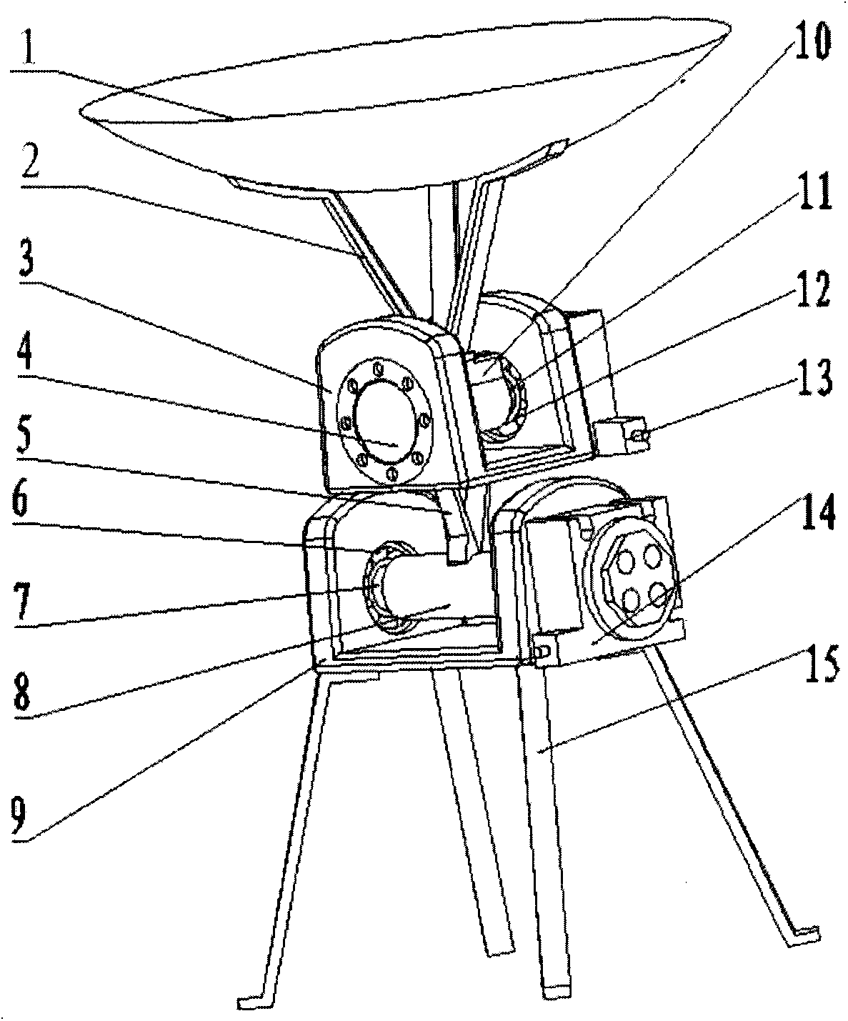
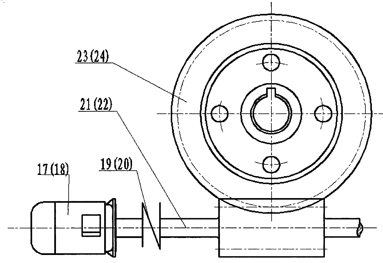
[0019] Such as figure 1 and figure 2 As shown, the installation method of each component in the present invention is: the solar receiving plate 1 and the receiving plate support frame 2, the receiving plate support frame 2 and the upper shaft hub 10 are consolidated into one, and the upper shaft hub 10 and the upper transmission shaft 11 pass through the flat The upper drive shaft 11 is connected with the output shaft of the upper precision deceleration module 13 through a coupling; the lower hub 8 and the upper swing support seat 3 are fixedly connected by the two ends of the upper swing support frame 5, and the lower hub 8 is connected to the lower The transmission shaft 7 is connected by a flat key, and the lower transmission shaft 7 is connected with the lower precision reduction module 14 by a shaft coupling. Such as figure 2 As shown, the upper precision deceleration module 13 and the lower precision deceleration module 14 are respectively externally connected with s...
Embodiment 2
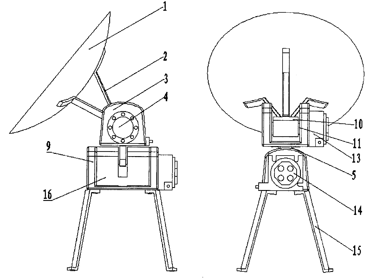
[0025] Figure 5 It is an embodiment of using a flat solar panel. Such as Figure 5 and figure 2 As shown, the installation method of each component in the present invention is: the solar receiving plate 1 and the receiving plate support frame 2, the receiving plate support frame 2 and the upper shaft hub 10 are consolidated into one, and the upper shaft hub 10 and the upper transmission shaft 11 pass through the flat The upper drive shaft 11 is connected with the output shaft of the upper precision deceleration module 13 through a coupling; the lower hub 8 and the upper swing support seat 3 are fixedly connected by the two ends of the upper swing support frame 5, and the lower hub 8 is connected to the lower The transmission shaft 7 is connected by a flat key, and the lower transmission shaft 7 is connected with the lower precision reduction module 14 by a shaft coupling. Such as figure 2 As shown, the upper precision deceleration module 13 and the lower precision decel...
PUM
 Abstract
Description
Claims
Application Information
PatSnap Eureka turns technology decisions into work you can execute. Powered by our Innovation Knowledge Graph, it runs expert workflows across engineering, life sciences, materials and intellectual property. Get your review-ready output in minutes.


