Intelligent dead point recognition and self-adaptation compensation method for infrared touch screen
An infrared touch screen and self-adaptive compensation technology, applied in the direction of instrumentation, electrical digital data processing, data processing input/output process, etc., can solve the problems of undetectable, unmentioned, cost increase, etc., to eliminate resolution reduction, The effect of increasing the working stability and prolonging the service life
- Summary
- Abstract
- Description
- Claims
- Application Information
AI Technical Summary
Problems solved by technology
Method used
Image

Examples
Embodiment Construction
[0032] A11. Record the serial number of the infrared tube at the current touch occlusion position into the occlusion information array BlindNUM[LED_NUM] every CountNum scanning cycle, and add 1 to the number of occlusion times corresponding to the serial number, and check whether there is a condition of BlindNUM[LED_NUM]>COVERTIME in the array established.
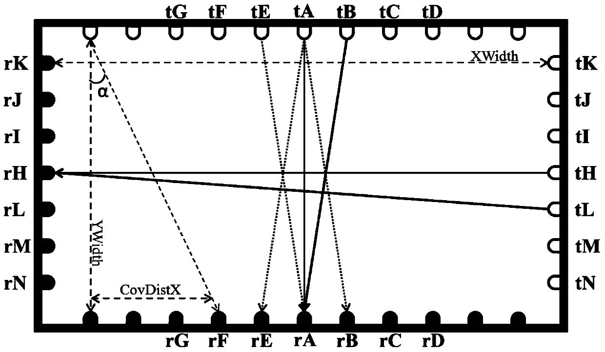
[0033] A12. If BlindNUM[A]>COVERTIME, it is determined that the infrared pair tube with serial number A has become a faulty tube due to its own damage or foreign objects, and record the serial number A into the dead point information array BadNUM[SUM].badNO=A. Among them, SUM is the total number of dead points, and A is figure 1 Infrared tube serial number of mid-infrared emitting tube tA and infrared receiving tube rA.
[0034] A2. Using the adjacent pair of infrared tubes with serial numbers B and E, use the oblique scanning method to determine whether the fault type of the faulty tube with serial number A is damaged by...
PUM
 Abstract
Description
Claims
Application Information
 - Generate Ideas
- Intellectual Property
- Life Sciences
- Materials
- Tech Scout
- Unparalleled Data Quality
- Higher Quality Content
- 60% Fewer Hallucinations
Browse by: Latest US Patents, China's latest patents, Technical Efficacy Thesaurus, Application Domain, Technology Topic, Popular Technical Reports.
© 2025 PatSnap. All rights reserved.Legal|Privacy policy|Modern Slavery Act Transparency Statement|Sitemap|About US| Contact US: help@patsnap.com