Sectional type load switch mechanism

A technology of load switch and switch mechanism, which is applied in the direction of electric switch, high-voltage/high-current switch, high-voltage air circuit breaker, etc., which can solve the problems of increasing energy utilization rate, reducing spring working stroke, increasing bounce, etc., so as to increase energy utilization The effect of reducing the working stroke and optimizing the output force

Active Publication Date: 2014-04-23
SHANGHAI PINGGAO TIANLING SWITCHGEAR CO LTD +1
View PDF3 Cites 12 Cited by
  • Summary
  • Abstract
  • Description
  • Claims
  • Application Information

AI Technical Summary

Problems solved by technology

[0007] Aiming at the existing environment-friendly load switchgear that uses vacuum arc extinguishing instead of sulfur hexafluoride, a large amount of work is wasted on the isolation stroke that does not require closing and opening speed requirements and has a large distance, and at the same time causes the closing speed to be too fast, making it easier to touch Head wear and increased bouncing, or adding an isolation knife mechanism, increases the cost. The present invention is to provide a segmented load switch operating mechanism. The operating mechanism divides the closing process into two sections to cooperate with isolation The different action requirements of the knife and the vacuum bubble reduce the working stroke of the spring, increase the energy utilization rate, and save costs; in addition, adding an elbow-shaped power-assisted closing output arm can make the load switch obtain a more optimized output force of the mechanism

Method used


Image

  • Sectional type load switch mechanism
  • Sectional type load switch mechanism
  • Sectional type load switch mechanism

Examples


Embodiment Construction

[0026] In order to make the technical means, creative features, goals and effects achieved by the present invention easy to understand, the present invention will be further described below in conjunction with specific illustrations.

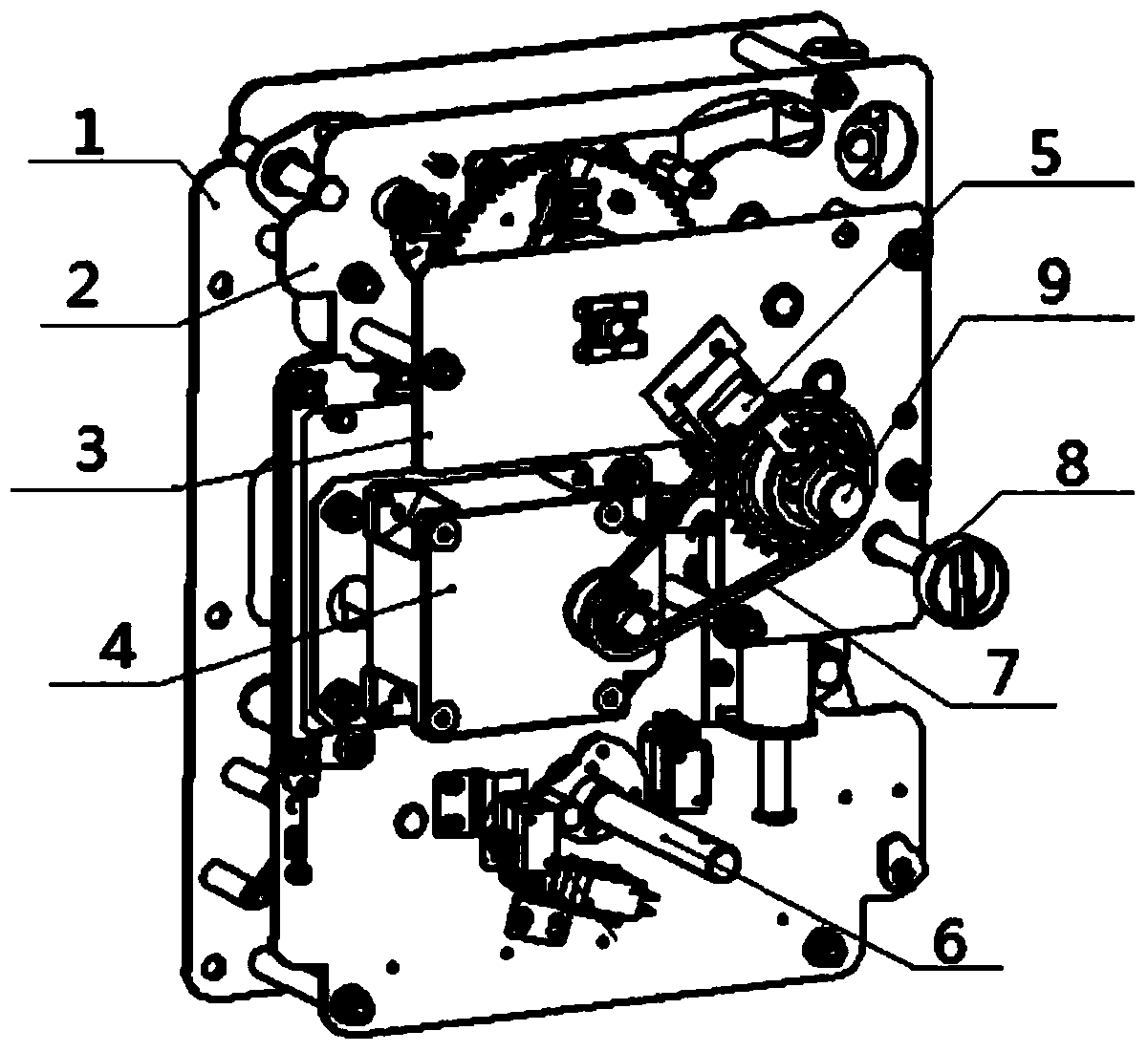
[0027] see figure 1 , the segmented load switch mechanism provided by the present invention includes a mechanism frame composed of a rear support plate (1), a middle support plate (2), and a front support plate (3). parts.

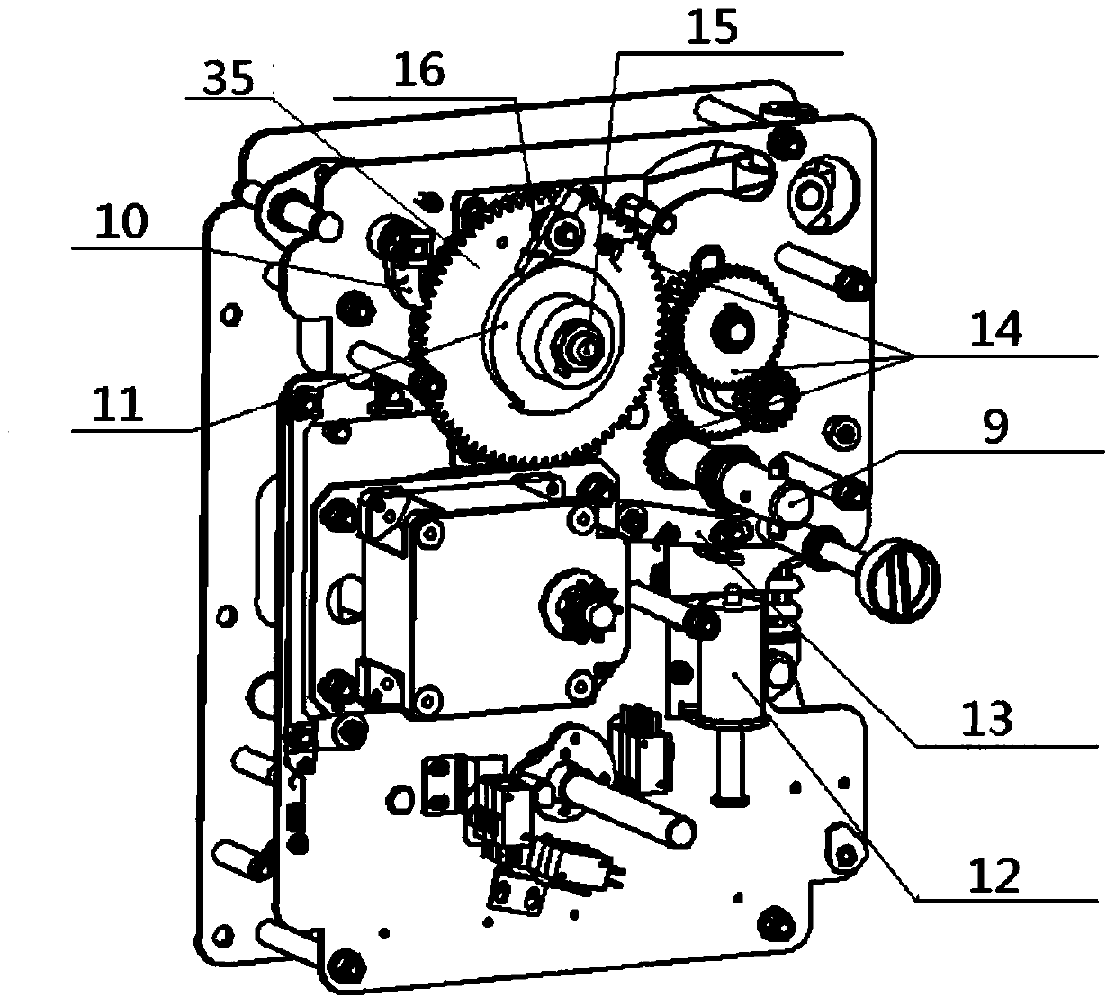
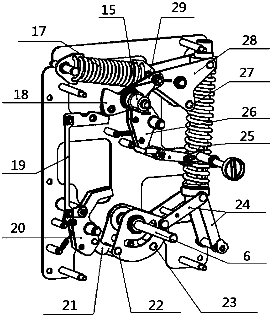
[0028] Depend on Figures 2 to 5 It can be seen that the components that make up the segmented load switch mechanism mainly include: motor (4), micro switch (5), output shaft with two-stage limit (6), manual trip knob (8), operating shaft (9 ), anti-reverse pawl (10), drive cam (11), electric opening trip coil (12), trip interlock plate (13), drive gear set (14), drive shaft (15), drive top block (16), opening spring (17), driving fan-shaped plate (18), automatic closing interlock device after energy storage (19), closing...


PUM


Abstract

The invention discloses a sectional type load switch mechanism. In the mechanism, an output shaft is provided with a first-stage limiting pin and a second-stage limiting pin, the segment motion mode of a main shaft is realized through cooperating with a switching-on interlocking device, a switching-on limiting device and a unidirectional limiting block disposed on the switching-on limiting device, and an elbow type power-assisted switching-on output connecting lever is utilized to enable the main shaft to provide a larger output force in a final switching-on process when a force is more needed in case of a closer switching-on finishing position; at the same time, when switching-on is put in place, the elbow type output connecting lever is distributed in the form of a horizontal connecting rod, and self-locking is formed; and a driving sector plate on one hand provides a release signal for two-stage motion of the output shaft, and on the other hand performs energy storage on a switching-off spring and enables the switching-off spring to maintain at a main shaft switching-on state through a connection plate, a switching-off interlocking plate, a switching-off limiting pin and a switching-off limiting device. The operation mechanism, through dividing a switching-on process into two segments to respectively cooperate with different motion requirements of an isolation knife and a vacuum bubble, reduces the working stroke of the spring, improves energy utilization rate, and saves cost.

Description

technical field [0001] The invention relates to a switch electrical appliance used in a switch cabinet, in particular to a load switch. Background technique [0002] The load switch is a switching device between the circuit breaker and the isolating switch. It has a simple arc extinguishing device, which can cut off the rated load current, but cannot cut off the short-circuit current. The load switch operating mechanism is a set of mechanical devices that drive the output shaft of the load switch to move through the energy storage and release of the spring to realize the closing and opening of the load switch. [0003] In the current popular load switch cabinets, the environment-friendly load switch cabinet is the direction of development, and in today's environment-friendly load switch cabinets (without SF6), most of them use vacuum bubble switches, and vacuum arc extinguishing replaces the previous ones. Sulfur hexafluoride gas arc extinguishing, although the opening dist...

Claims


Application Information

Patent Timeline
Patent Type & Authority Applications(China)
IPC IPC(8): H01H33/40H01H33/46
Inventor 陆逸王陆一
Owner SHANGHAI PINGGAO TIANLING SWITCHGEAR CO LTD
Why Eureka
Try Eureka