Hydraulic push-in replacing device for current transformer

A current transformer, push-in technology, used in lifting devices, switch devices, electrical components, etc., can solve problems such as damage to staff or equipment, low work efficiency, poor safety, etc., to achieve no maintenance costs and improve work efficiency. , the effect of moving stability

Inactive Publication Date: 2014-04-23
STATE GRID CORP OF CHINA +1
View PDF5 Cites 4 Cited by
  • Summary
  • Abstract
  • Description
  • Claims
  • Application Information

AI Technical Summary

Problems solved by technology

The disadvantages of this method are obvious. The first is that more manpower is required. The second is that the safety is poor and it is easy to cause damage to the staff or the equipment itself. The third is that it is not convenient enough, the work efficiency is low, and it takes a long time.

Method used


Image

  • Hydraulic push-in replacing device for current transformer

Examples


Embodiment Construction

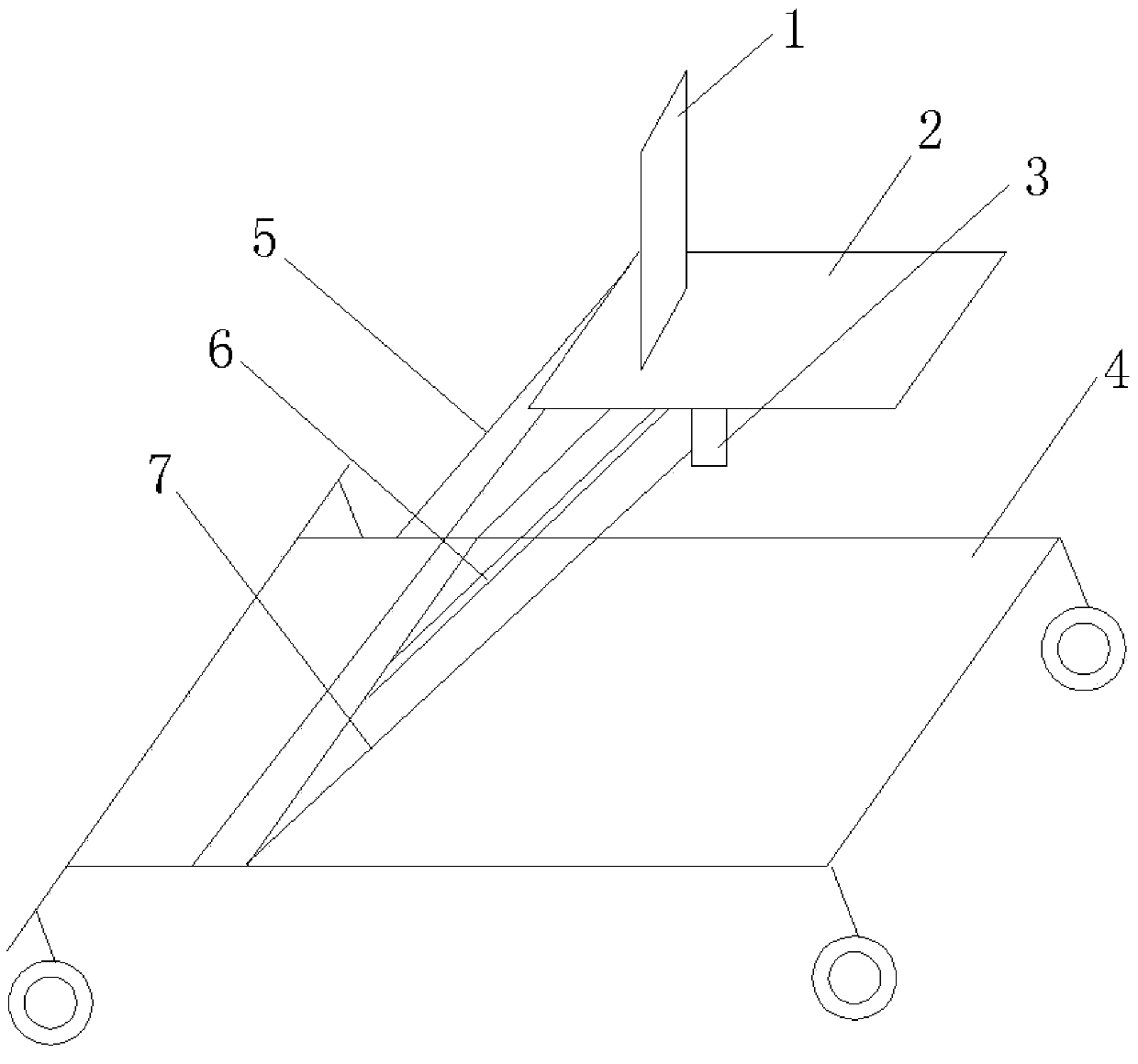
[0014] Such as figure 1 As shown, the present invention is a hydraulic push-in type current transformer replacement device, including a base 4, on which a hydraulic jack 6 is fixedly installed, and a support column 7 is respectively installed on both sides of the hydraulic jack 6, wherein The bottom of every support column 7 is all hinged on the base 4, and also includes a support platform, on the lower surface of the support platform, a connecting frame 3 is fixed, and the connecting frame 3 is hinged together with the piston rod head of the aforementioned hydraulic jack 6 , and the connecting frame 3 is also hinged together with the tops of the two supporting columns 7 .

[0015] Wherein the angle between the hydraulic jack 6 and the base 4 is 45-80 degrees, for example, the angle is 70 degrees, the base 4 is a rectangle, and two universal wheels and two universal wheels are respectively installed on the four corners of the base 4 Orientation wheel. The base 4 is specifica...


PUM


Abstract

The invention relates to a hydraulic push-in replacing device for a current transformer. The hydraulic push-in replacing device for the current transformer is characterized by comprising a base (4). The base (4) is fixedly provided with a hydraulic jack (6); both sides of the hydraulic jack (6) are respectively provided with a support pillar (7); the bottom part of each support pillar (7) is hinged to the base (4). The hydraulic push-in replacing device for the current transformer also comprises a support platform. The lower bottom face of the support platform is fixedly provided with a connecting yoke (3); the connecting yoke (3) and the head part of a piston rod of the hydraulic jack (6) are hinged together, and meanwhile, the connecting yoke (3) and top parts of the two support pillars (7) are also hinged together. After the replacing device provided by the invention is adopted, manual operation is replaced. The replacing device is stable in movement, convenient to use, low in cost and basically free of maintenance cost in the later period. Workers can be reduced to 2 persons, so that the replacing time of the current transformer is greatly shortened, the working performance is improved, and the power supply reliability is ensured.

Description

technical field [0001] The invention relates to a hydraulic push-in type current transformer replacement device. Background technique [0002] At present, when electric workers need to replace the current transformer of the switchgear, it often requires the cooperation of multiple people, and the operation is performed by manpower lifting and replacement. The disadvantages of doing this are obvious. The first is that more manpower is needed, the second is that the safety is poor, and it is easy to cause damage to the staff or the equipment itself. The third is that it is not convenient enough, the work efficiency is low, and it takes a long time. Contents of the invention [0003] The purpose of the present invention is to provide a hydraulic push-in type current transformer replacement device, which can shorten the replacement time of the current transformer and improve the safety of personnel and equipment. [0004] A hydraulic push-in type current transformer replaceme...

Claims


Application Information

Patent Timeline
Patent Type & Authority Applications(China)
IPC IPC(8): H02B3/00B66F7/18
Inventor 应东朱茜李庆华陈鸿岩薛东王颖张灏
Owner STATE GRID CORP OF CHINA
Why Eureka
Try Eureka